CAUTION: The switch can only be adjusted once.
That is during initial installation of the switch. If the
switch is not adjusted properly or has been
removed for any reason, a new switch must be
installed and adjusted.
REMOVAL
(1) Disconnect and isolate battery negative cable
from its post on battery.
(2) Under instrument panel, remove brake lamp
switch by rotating switch in counterclockwise direc-
tion approximately 30 degrees and pulling it out of
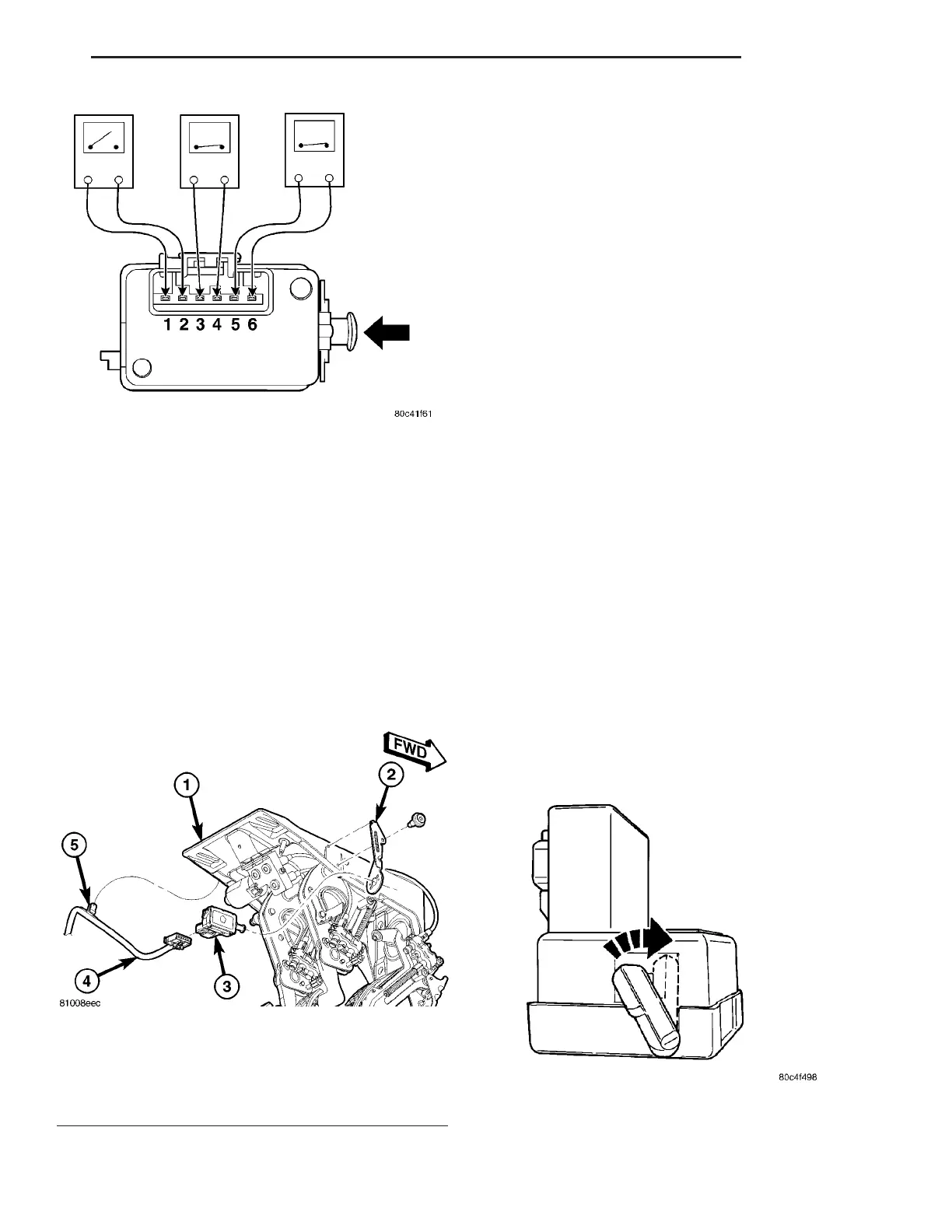
bracket (Fig. 3).
(3) Disconnect wiring harness connector from
switch (Fig. 3).
(4) Discard brake lamp switch. It must not be
reused.
INSTALLATION
CAUTION: Do not reuse the original brake lamp
switch. This switch can only be adjusted once. That
is during initial installation of the switch. If the
switch is not adjusted properly or has been
removed for some service, a new switch must be
installed and adjusted.
(1) Obtain NEW brake lamp switch. Adjustment
lever on new switch should be at a 45° angle from
wiring connector. If adjustment lever is parallel
with wiring connector, switch has been preset
and must be scrapped. DO NOT ATTEMPT TO
RESET (OR READJUST) BRAKE LAMP
SWITCH.
(2) Connect wiring harness to connector on switch
(Fig. 3).
(3) Mount and adjust NEW brake lamp switch
using following steps:
(a) Install switch in its bracket by aligning the
index tab on switch with notch in mounting
bracket.
(b) When switch body is fully seated in its
bracket, rotate switch clockwise approximately 30°
to lock switch into place.
(c) With brake pedal in fully released position,
move adjustment lever on brake lamp switch from
45° angled non-adjusted position, clockwise as
shown, until it is parallel with wiring connector
(Fig. 4). Brake lamp switch is now properly
adjusted to vehicle.
(4) Reconnect battery negative cable to post on
battery.
Fig. 2 SWITCH TEST - DEPRESSED POSITION
Fig. 3 Brake Lamp Switch Mounting
1 - ADJUSTABLE PEDALS ASSEMBLY
2 - SWITCH BRACKET
3 - BRAKE LAMP SWITCH
4 - WIRING HARNESS
5 - CLIP
Fig. 4 Adjustment Lever Movement
ZB LAMPS 8L - 5
BRAKE LAMP SWITCH (Continued)















 To Next Page