There are three components to each of the HID
headlamps:
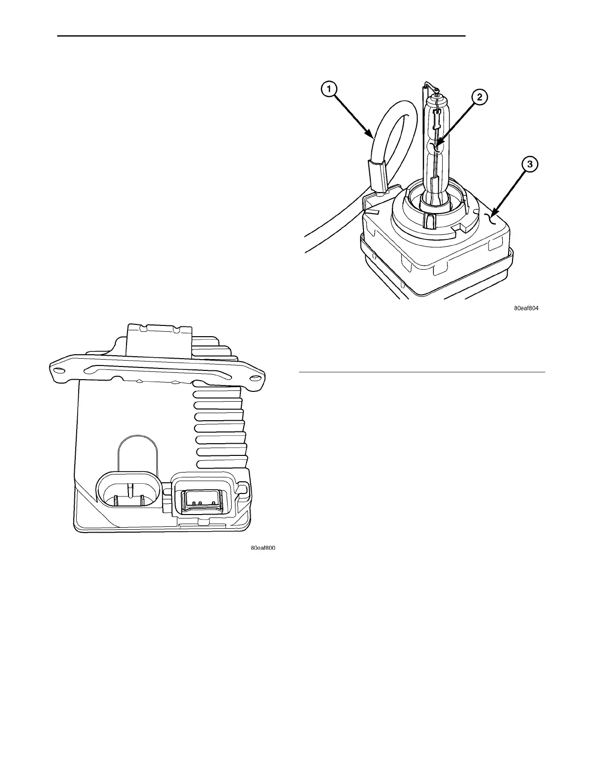
• Ballast Module - The 12 volt Direct Current
(DC) power supplied by the low beam relay is con-
verted to Alternating Current (AC) power by the bal-
last module (Fig. 10). Each lamp requires its own
ballast. The ballast converts and steps up the low
beam relay output to 800 volts AC, and supplies the
lamp assembly via a cable connected to the igniter.
• Igniter - The lamp assembly contains an igniter
(Fig. 11) that controls the voltage applied to the lamp
electrodes. The igniter uses the voltage supplied by
the ballast and momentarily steps up the voltage to
25,000 volts to start the lamp. Once ignited, it will
reduce the voltage to 85 volts.
• Lamp - The lamp (Fig. 11) contains electrodes
and xenon gas. The lamp takes about 10-15 seconds
of warm-up time to reach full operation. The light
appears blue during warm-up and then turns to
white.
DIAGNOSIS AND TESTING - HIGH INTENSITY
DISCHARGE HEADLAMPS
The High Intensity Discharge (HID) headlamps are
supplied B+ voltage and ground, the same as normal
halogen low beam lamps. The low beam system is
different from there forward. The ballast module is
mounted to the inside of the headlamp unit access
cover. The ballast module has internal circuit protec-
tion to prevent module damage in case of an open or
shorted circuit. The module has overcharge and
undercharge circuit protection. If either is sensed,
the module will not illuminate the headlamps for
that key cycle or until the fault is corrected. Recycle
the ignition and headlamp switch if both headlamps
do not illuminate and the fuse is OK. Before deter-
mining the headlamp assembly is faulty, check the
connector at the headlamp and the low beam fuse in
the Power Distribution Center (PDC). Check the
BCM for any faults on the park, high beam & fog
lamp outputs and the low beam relay coil. If the
BCM senses any short conditions, it will disable
these outputs until the next ignition On/Off cycle. If
the ballast module senses a short or open circuit con-
dition, it will not operate the lamp/igniter.
The headlamp unit assembly must be removed to
perform the following tests (Refer to 8 - ELECTRI-
CAL/LAMPS/LIGHTING - EXTERIOR/HEADLAMP
UNIT - REMOVAL).
(1) Inspect lamp/igniter assembly for a burned out
lamp. If lamp is burned out it will appear black or
smoky, similar to a normal halogen bulb. If lamp
looks OK, go to Step 2.
(2) Check for B+ battery voltage at the two pin
connector going into the ballast module. Refer to Wir-
ing Diagrams for connector location. If battery volt-
age and a good ground are present, go to Step 3. If
B+ voltage and a good ground are not present, refer
to Wiring Diagrams for circuit and connector loca-
tions to find short or open circuit.
(3) Plug in a known good ballast module and check
for lamp operation. If lamp lights, replace ballast
Fig. 10 HID BALLAST MODULE
Fig. 11 HID LAMP AND IGNITER
1 - CABLE
2 - LAMP
3 - IGNITER
ZB LAMPS 8L - 9
HEADLAMP (Continued)















 To Next Page