REMOVAL
(1) Open deck lid.
(2) Remove four bolts to battery compartment
cover and remove cover.
(3) Disconnect and isolate the battery negative
cable.
(4) Open hood.
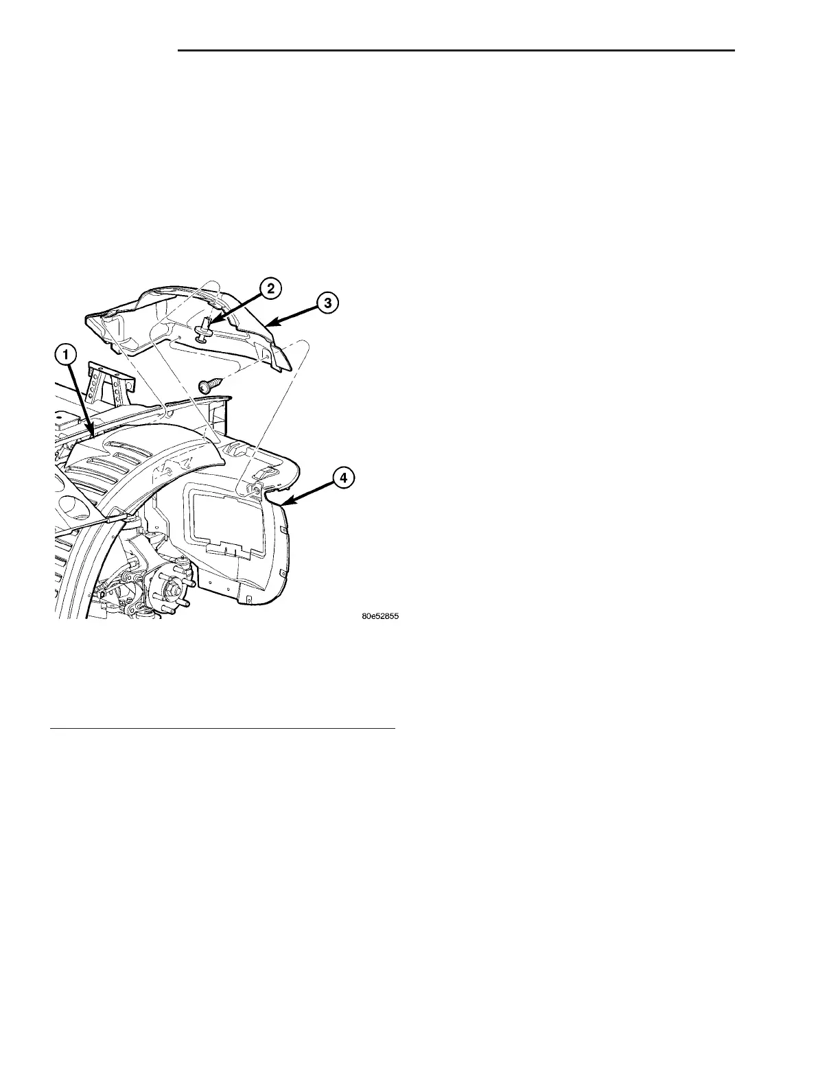
(5) Remove front fender extension splash shield on
the respective side by removing the fasteners (Fig.
14).
(6) From just inside the engine compartment, just
to the right of the air cleaner housing, find and dis-
connect the headlamp unit wiring harness connector.
When disconnected, feed wire through inner fender
into wheel well.
(7) Remove the four bolts to the fender along the
inner edge of the engine compartment to allow the
fender to be lifted slightly upon headlamp unit
removal.
(8) From inside the wheel well, remove the two
nuts and bracket that attach the corner of the fascia
to the fender.
(9) From the underside, remove the one screw that
attaches the fender to the fascia support panel.
(10) Remove the three retaining nuts from the
underside of the headlamp unit.
(11) Lift up on the front of the fender slightly, then
lift the headlamp unit up and to the rear, into the
wheel well.
NOTE: Be careful not to lose the shims (if they are
present) they will be needed upon installation for
the proper headlamp unit alignment.
INSTALLATION
(1) If replacing headlamp unit, transfer the bulbs
to the new headlamp unit.
(2) Maneuver headlamp unit in the wheel well
opening and forward into the headlamp unit mount-
ing slots.
NOTE: If shims were present at removal, then rein-
sert the shims in the same place before tightening
headlamp unit nuts.
(3) Install the three retaining nuts on the under-
side of the headlamp unit. Torque nuts to 10 N·m (85
in. lbs.).
Install the one screw that attaches the fender to
the fascia support panel.
(4) Install the bracket and two nuts for the fender/
fascia attachment.
(5) Install the front fender extension splash shield
on the respective side by and the fasteners (Fig. 14).
(6) Connect the battery negative cable.
(7) Place battery access cover into place and install
four bolts.
(8) Close deck lid.
(9) Verify vehicle and system operation.
(10) Verify headlamp unit aim. If adjustment is
necessary, (Refer to 8 - ELECTRICAL/LAMPS/
LIGHTING - EXTERIOR/HEADLAMP UNIT -
STANDARD PROCEDURE).
LICENSE PLATE LAMP
REMOVAL
(1) Open deck lid.
(2) Remove four bolts to battery compartment
cover and remove cover.
(3) Disconnect and isolate the battery negative
cable.
(4) Reach in behind the license plate lamp unit
and turn the respective bulb counterclockwise, pull
forward and remove.
(5) Pull the license plate lamp straight out and
remove from vehicle.
INSTALLATION
(1) Push the license plate lamp straight into the
lamp socket.
Fig. 14 FRONT FENDER EXTENSION SPLASH
SHIELD
1 - FENDER SPLASH SHIELD
2 - PUSH IN PIN FASTENER
3 - FENDER EXTENSION SPLASH SHIELD
4 - FRAME ASSEMBLY
8L - 14 LAMPS ZB
HEADLAMP UNIT (Continued)















 To Next Page