CONDITION POSSIBLE CAUSES CORRECTION
SYSTEM DOES NOT CANCEL
AFTER COMPLETION OF THE
TURN.
(1) BROKEN CANCELLING FIN-
GER ON SWITCH.
(1) REPLACE MULTI FUNCTION
SWITCH.
(2) BROKEN OR MISSING
CANCELLING CAM ON CLOCK
SPRING.
(2) REPLACE CLOCK SPRING.
EXTERNAL LAMPS OPERATE
PROPERLY, NO INDICATOR
LAMP OPERATION.
(1) FAULTY INDICATOR LAMP
IN INSTRUMENT CLUSTER.
(1) REPLACE LAMP.
(2) OPEN CIRCUIT OR WIR-
ING.
(2) REPAIR WIRING HARNESS.
SWITCH DIAGNOSIS
To test the switch:
(1) Disconnect and isolate the battery negative
cable.
(2) Remove the upper and lower steering column
shrouds.
(3) Disconnect the switch connector.
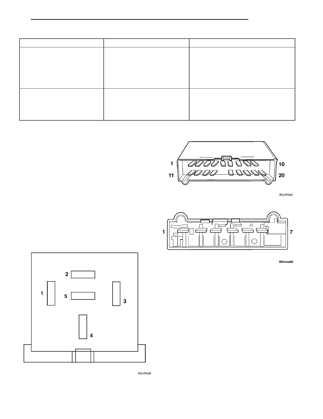
Using an ohmmeter, test for continuity (no resis-
tance) between the terminals of the switch as shown
in the Multi-Function Switch Continuity Test table
for diagnosis. Refer to (Fig. 16), (Fig. 17), and (Fig.
18)for connector terminal locations.
NOTE: If the ohmmeter shows resistance values
greater then 1000 ohms, then the multi-function
switch is considered defective and must be
replaced.
Fig. 16 COMBINATION FLASHER CONNECTOR (A)
Fig. 17 MULTI-FUNCTION SWITCH CONNECTOR (B)
Fig. 18 WINDSHIELD WIPER/WASHER SWITCH
CONNECTOR (C)
ZB LAMPS 8L - 19
MULTI-FUNCTION SWITCH (Continued)















 To Next Page