INSTALLATION
(1) Connect wire harness connector and position
module into place.
(2) Install mounting fasteners.
(3) Install the instrument cluster (Refer to 8 -
ELECTRICAL/INSTRUMENT CLUSTER - INSTAL-
LATION).
(4) Connect the battery negative cable.
REMOTE KEYLESS ENTRY
TRANSMITTER
DIAGNOSIS AND TESTING - REMOTE KEYLESS
ENTRY TRANSMITTER
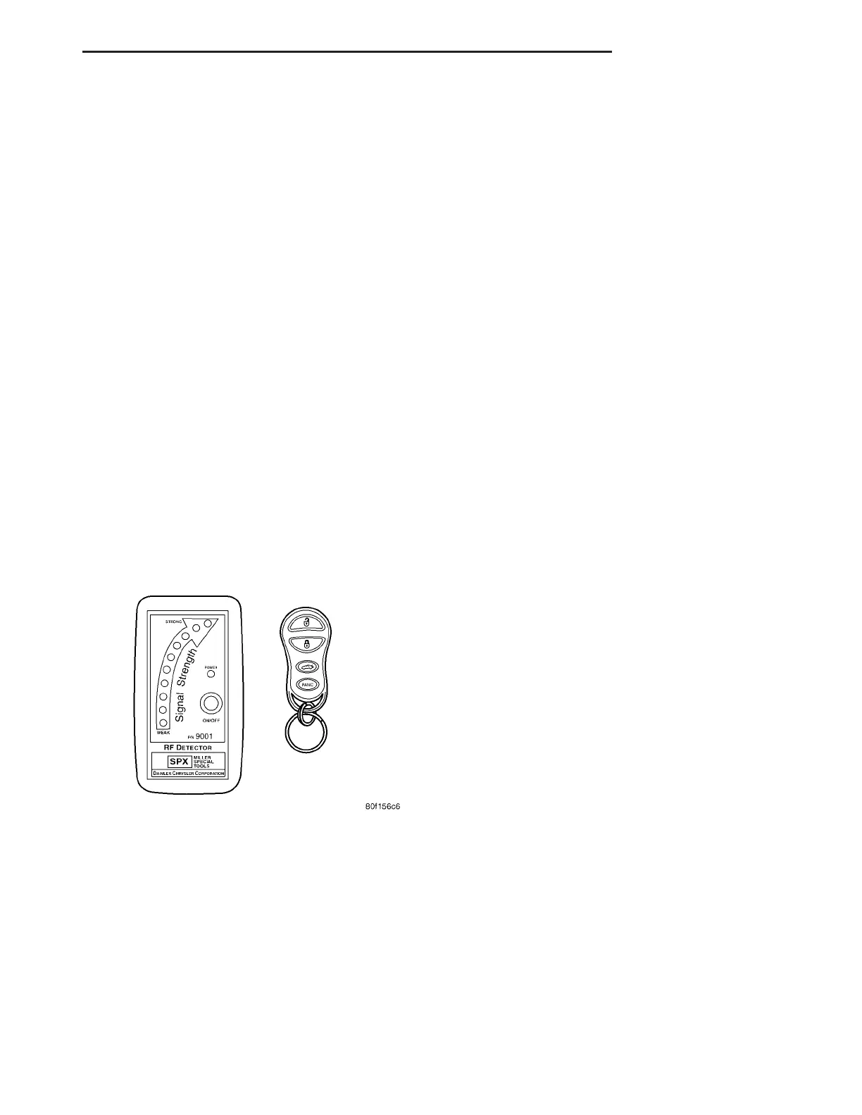
Using special tool 9001, first test to ensure that
the transmitter is functioning. Typical testing dis-
tance is 2.5 centimeters (1 inch) for Asian transmit-
ters and 30.5 centimeters (12 inches) for all others.
To test, position the transmitter as shown (Fig. 3).
Press any transmitter button, then test each button
individually. The tool will beep if a radio signal
strength that lights five or more LED’s is detected.
Repeat this test three times. If transmitter fails any
of the test, refer to the Diagnostic Procedures man-
ual.
STANDARD PROCEDURE
STANDARD PROCEDURE - RKE TRANSMITTER
BATTERIES
NOTE: Do not disturb the metal terminal near the
batteries. Avoid touching the new batteries. Skin
oils may cause battery deterioration. If batteries are
touched, clean with rubbing alcohol.
The Remote Keyless Entry (RKE) transmitter case
snaps open and shut for battery access. To replace
the RKE transmitter batteries:
(1) Using a thin coin, gently pry at the notch in
the center seam of the RKE transmitter case halves
near the key ring until the two halves unsnap. Be
careful not to damage the rubber gasket when sepa-
rating the case halves.
(2) Lift the back half of the transmitter case off of
the RKE transmitter.
(3) Remove the two batteries from the RKE trans-
mitter.
(4) Replace the two batteries with new 3V Pana-
sonic CR2032 or equivalent. Install the batteries with
the positive terminal up. Reference the “+ SIDE UP”
on the inside of the bottom half of the transmitter
case.
(5) Align the two RKE transmitter case halves
with each other, and squeeze them firmly and evenly
together until they snap back into place. Test trans-
mitter operation.
STANDARD PROCEDURE - RKE TRANSMITTER
CUSTOMER PREFERENCES
AUTOMATIC (ROLLING) LOCKS
The rolling locks feature can be toggled ON/OFF
by using the DRB IIIt only.
HORN CHIRP DISABLING / ENABLING
The horn chirp can be toggled using a DRB IIIt or
by using the Remote Keyless Entry (RKE) transmit-
ter that is already programmed to the vehicle.
To DISABLE (cancel) the horn chirp feature:
(1) Press and hold the LOCK button for 4 seconds.
Within 6 seconds with the LOCK button still
depressed, press the UNLOCK button.
(2) Test the horn chirp feature by pressing the
LOCK button.
To ENABLE the horn chirp feature, repeat the
above procedure.
OPTICAL CHIRP (FLASH) DISABLING / ENABLING
The optical chirp can be toggled using a DRB IIIt
or by using the Remote Keyless Entry (RKE) trans-
mitter that is already programmed to the vehicle.
To DISABLE (cancel) the optical chirp feature:
(1) Press and hold the LOCK button for 4 seconds.
Within 10 seconds with the LOCK button still
depressed, press the TRUNK button. When a single
chime is heard, release both buttons.
(2) Test the optical chirp feature by pressing the
LOCK button and noting if the park lamps flash.
To ENABLE the optical chirp feature, repeat the
above procedure.
Fig. 3 REMOTE KEYLESS ENTRY TRANSMITTER
DIAGNOSIS
ZB POWER LOCKS 8N - 5
REMOTE KEYLESS ENTRY MODULE (Continued)
 Loading...


