(3) Use an ohmmeter to test switch resistance
between pins.
(4) Pull handle.
(5) Test resistance between pins. Ohmmeter should
show 3.5K Ohm ± 5%.
(6) Test resistance between pins while handle is in
the unactuated mode. Ohmmeter should show an
open condition.
(7) If resistance values are not within the param-
eters, replace the interior door handle.
POWER LOCK SWITCH
DIAGNOSIS AND TESTING - POWER LOCK
SWITCH
Any diagnosis of the Power Locks system
should begin with the use of a scan tool and the
appropriate Diagnostic Service Manual.
Refer to the appropriate wiring information.
(1) Remove the power lock switch (Refer to 8 -
ELECTRICAL/POWER LOCKS/POWER LOCK
SWITCH - REMOVAL).
(2) Depress switch to LOCK position.
(3) Using an ohmmeter and the door lock switch
continuity chart, test switch resistance between Pins
2 and 3 (Fig. 1).
(4) Depress switch to UNLOCK position.
(5) Test resistance between Pins 2 and 3.
(6) Test resistance between pins 2 and 3 while
switch is in the unactuated mode. Ohmmeter should
show an open condition.
(7) If resistance values are not within the param-
eters shown, replace the door lock switch.
DOOR LOCK SWITCH CONTINUITY
SWITCH
POSITION
CONTINUITY
BETWEEN
RESISTANCE
VALUE
LOCK 2 and 3 1.5K Ohm ± 5%
UNLOCK 2 and 3 249 Ohm ± 5%
UNACTUATED 2 and 3 Open Circuit
REMOVAL
(1) Disconnect and isolate the battery negative
cable.
(2) Remove the door trim panel (Refer to 23 -
BODY/DOOR - FRONT/TRIM PANEL - REMOVAL).
(3) Remove mounting fasteners and switch.
INSTALLATION
(1) Install switch and mounting fasteners to door
trim panel.
(2) Install door trim panel (Refer to 23 - BODY/
DOOR - FRONT/TRIM PANEL - INSTALLATION).
(3) Connect battery negative cable.
REMOTE KEYLESS ENTRY
MODULE
DIAGNOSIS AND TESTING - REMOTE KEYLESS
ENTRY MODULE
Any diagnosis of the Power Locks system
should begin with the use of a scan tool and the
appropriate Diagnostic Service Manual.
Refer to the appropriate wiring information.
REMOVAL
(1) Disconnect and isolate the battery negative
cable.
(2) Remove the instrument cluster (Refer to 8 -
ELECTRICAL/INSTRUMENT CLUSTER -
REMOVAL).
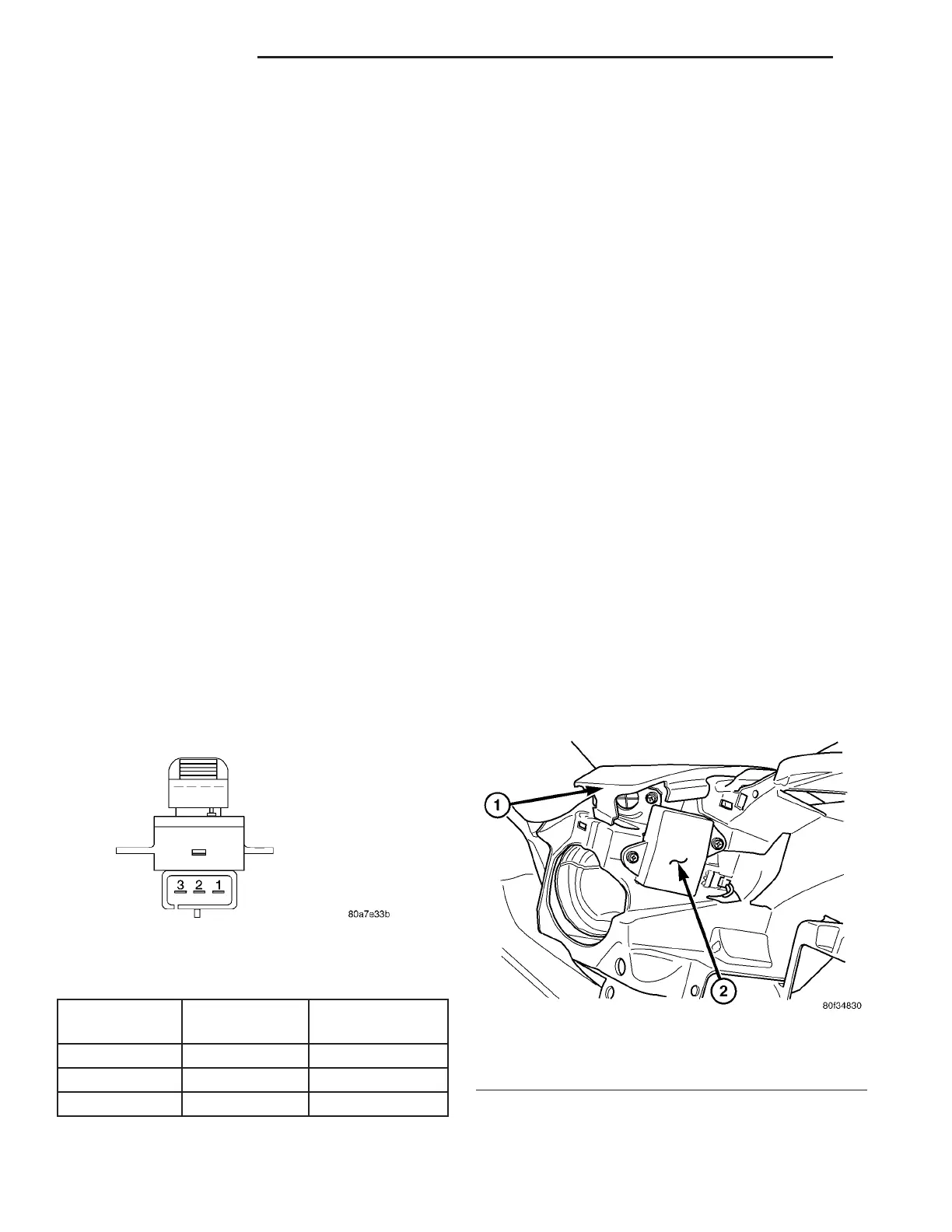
(3) Remove the mounting fasteners (Fig. 2)
(4) Disconnect wire harness connector and remove
module.
Fig. 1 DOOR LOCK SWITCH
Fig. 2 REMOTE KEYLESS ENTRY MODULE
1 - LEFT INSTRUMENT PANEL SPEAKER
2 - RKE MODULE
8N - 4 POWER LOCKS ZB
INTERIOR DOOR HANDLE SWITCH (Continued)
 Loading...


