NOTE: Use of Spacer, Special Tool 6983, is neces-
sary to allow proper use of Puller, Special Tool
C-4150A, to release lower ball joint from knuckle.
(8) Insert Spacer, Special Tool 6983, between lower
ball joint grease seal and steering knuckle (Fig. 8).
Push Spacer in until it surrounds ball joint stud.
CAUTION: When releasing ball joint from knuckle
using Puller, Special Tool C-4150A, use care not to
pinch and damage ball joint grease seal.
(9) Install Puller, Special Tool C-4150A, over
Spacer and knuckle as shown (Fig. 9). Ball bearing
in bolt of Special Tool C-4150A must be cen-
tered in end of lower ball joint stud.
(10) Release lower ball joint from knuckle using
Puller. Remove tools.
(11) Remove cotter pin and castle nut from upper
ball joint stud (Fig. 6).
(12) Install Puller, Special Tool C-4150A, and
release upper ball joint from knuckle. Ball bearing
in bolt of Special Tool C-4150A must be cen-
tered in end of lower ball joint stud. Remove
tool.
(13) Remove steering knuckle from upper and
lower control arms.
(14) If hub and bearing needs to be removed from
knuckle, perform the following:
(a) Remove bolt retaining ABS tone wheel to hub
and bearing (Fig. 11).
(b) Remove ABS tone wheel (Fig. 11).
(c) Remove four hub and bearing mounting bolts
(Fig. 4).
(d) Remove hub and bearing assembly from
knuckle.
INSTALLATION
(1) If hub and bearing are removed from knuckle,
perform the following:
(a) Install a new corrosion prevention gasket on
hub and bearing mounting flange before installing
hub and bearing (Fig. 13).
(b) Install hub and bearing (with gasket) in
steering knuckle. Align holes in corrosion preven-
tion gasket with holes in hub and bearing, and
knuckle.
(c) Install four mounting bolts (Fig. 4) and
tighten bolts to 61 N·m (45 ft. lbs.) torque.
(d) Make sure ABS wheel speed sensor tone
wheel seal is installed in rear of knuckle. If seal is
missing or damaged, install a new seal. (Refer to 2
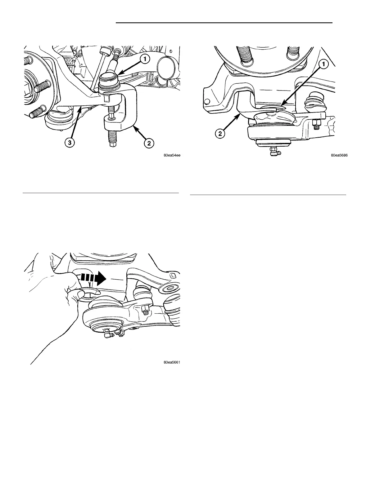
Fig. 7 Puller Positioned To Release Tie Rod
1 - OUTER TIE ROD
2 - PULLER C-4150A
3 - KNUCKLE
Fig. 8 Inserting Spacer Between Knuckle And Seal
Fig. 9 Puller And Spacer Positioned To Release Ball
Joint
1 - SPACER 6983
2 - PULLER C-4150A
2 - 8 FRONT SUSPENSION ZB
KNUCKLE (Continued)