- SUSPENSION/FRONT/KNUCKLE / ABS TONE
WHEEL SEAL - INSTALLATION)
(e) Install ABS wheel speed sensor tone wheel
through seal on rear of knuckle and against rear of
hub and bearing (Fig. 11). Install and tighten
mounting bolt to 17 N·m (13 ft. lbs.) torque.
(2) Install steering knuckle on lower ball joint
stud. Loosely install castle nut on stud (Fig. 6).
(3) Install steering knuckle on upper ball joint
stud. Loosely install castle nut on stud (Fig. 6).
(4) Install outer tie rod onto steering knuckle (Fig.
6). Install a NEW tie rod nut. Tighten nut to 75 N·m
(55 ft. lbs.) torque.
(5) Tighten upper ball joint castle nut to 102 N·m
(75 ft. lbs.) torque. Once nut is tightened to spec-
ified torque, it may be necessary to continue
tightening nut to allow installation of cotter
pin through nut castle and hole in ball joint
stud (DO NOT LOOSEN NUT).
(6) Install cotter pin through upper ball joint cas-
tle nut and stud.
(7) Tighten lower ball joint castle nut to 160 N·m
(118 ft. lbs.) torque. Once nut is tightened to spec-
ified torque, it may be necessary to continue
tightening nut to allow installation of cotter
pin through nut castle and hole in ball joint
stud (DO NOT LOOSEN NUT).
(8) Install cotter pin through lower ball joint castle
nut and stud.
(9) Install ABS wheel speed sensor in steering
knuckle (Fig. 10). Install and tighten mounting bolt
to 11 N·m (100 in. lbs.) torque.
(10) Install brake rotor and brake caliper on
knuckle. (Refer to 5 - BRAKES/HYDRAULIC/ME-
CHANICAL/ROTOR - INSTALLATION)
(11) Install wheel and tire assembly (Refer to 22 -
TIRES/WHEELS - INSTALLATION). Progressively
tighten wheel mounting nuts in proper sequence to
122 N·m (90 ft. lbs.) torque.
(12) Lower vehicle.
(13) Position vehicle on alignment rack/drive-on
hoist.
(14) Perform wheel alignment (Refer to 2 - SUS-
PENSION/WHEEL ALIGNMENT - STANDARD
PROCEDURE).
(15) Road test vehicle to ensure proper operation.
KNUCKLE/ABS TONE WHEEL
SEAL
REMOVAL
(1) Raise vehicle. (Refer to LUBRICATION &
MAINTENANCE/HOISTING - STANDARD PROCE-
DURE)
(2) Remove wheel and tire assembly. (Refer to 22 -
TIRES/WHEELS - REMOVAL)
(3) Remove brake caliper from knuckle and hang
out of way, then remove brake rotor. (Refer to 5 -
BRAKES/HYDRAULIC/MECHANICAL/ROTOR -
REMOVAL)
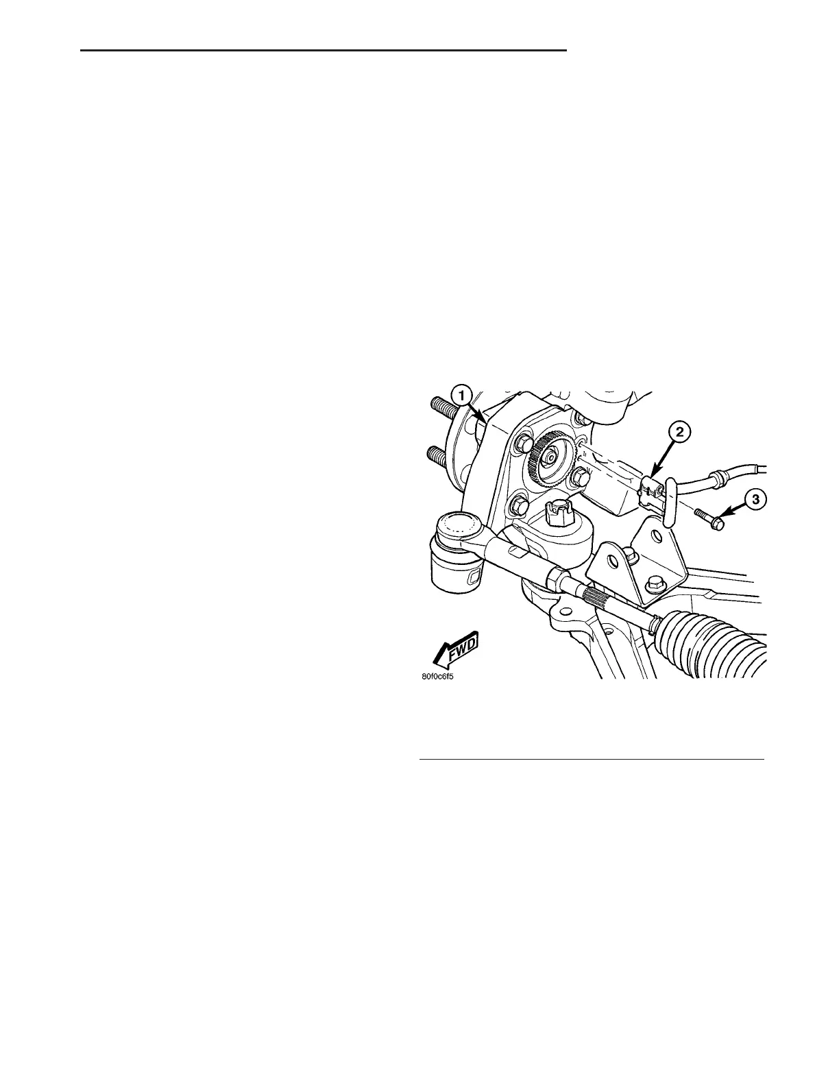
(4) Remove bolt fastening wheel speed sensor head
to steering knuckle (Fig. 10). Remove sensor head
from knuckle.
Fig. 10 Front Wheel Speed Sensor Mounting
1 - KNUCKLE
2 - WHEEL SPEED SENSOR
3 - MOUNTING BOLT
ZB FRONT SUSPENSION 2 - 9
KNUCKLE (Continued)