INSTALLATION
CAUTION: A corrosion prevention gasket is used
between the hub and bearing and the knuckle (Fig.
8). The gasket is required to prevent galvanic cor-
rosion between the hub and bearing and the
knuckle.
(1) Install NEW corrosion prevention gasket on
hub and bearing before installation (Fig. 8).
(2) Install hub and bearing on knuckle. Align holes
in hub and bearing and corrosion gasket with holes
in knuckle.
(3) Install four hub and bearing mounting bolts.
Tighten bolts to 149 N·m (110 ft. lbs.) torque.
(4) Install upper control arm ball joint stud into
mounting hole in knuckle. Install ball joint castle nut
and tighten to 102 N·m (75 ft. lbs.) torque.
(5) Install cotter pin in end of upper joint stud.
(6) Remove knuckle and upper control arm from
vise and install on vehicle. Slide hub and bearing
onto halfshaft yoke and guide upper control arm into
frame brackets.
(7) Install both upper control arm frame pivot
bolts and nuts (Fig. 9). Do not tighten at this
time.
(8) Install lower ball joint into lower control arm
(Fig. 3). Install ball joint castle nut, but do not
tighten at this time.
(9) Install toe link into mounting hole on knuckle
(Fig. 4). Install NEW nut on toe link stud and
tighten to 75 N·m (55 ft. lbs.) torque.
(10) Install plastic appearance cap on toe link
stud.
(11) Tighten lower ball joint castle nut to 160 N·m
(118 ft. lbs.) torque.
(12) Install cotter pin in end of lower ball joint
stud.
(13) Install washer and hub nut on halfshaft yoke
(Fig. 3). Do not tighten at this time.
(14) Install brake rotor, parking brake caliper and
hydraulic brake caliper on knuckle. (Refer to 5 -
BRAKES/HYDRAULIC/MECHANICAL/ROTOR -
INSTALLATION)
(15) Install ABS wheel speed sensor head on
knuckle (Fig. 2). Install bolt fastening speed sensor
head to knuckle and tighten to 11 N·m (100 in. lbs.)
torque.
(16) Lower vehicle just enough to gain access to
interior. Do not lower completely at this time.
(17) Apply brakes several times to seat brake
shoes and actuate parking brake lever several times
to equalize parking brake adjustment.
(18) Apply parking brake to keep halfshaft from
rotating while torquing hub nut.
(19) Tighten hub nut on halfshaft yoke to 258 N·m
(190 ft. lbs.) torque.
(20) Install spring washer, nut lock and cotter pin
on end of halfshaft yoke (Fig. 3).
(21) Install tire and wheel assembly (Refer to 22 -
TIRES/WHEELS - INSTALLATION). Progressively
tighten wheel mounting nuts in proper sequence to
122 N·m (90 ft. lbs.) torque.
(22) Lower vehicle.
(23) Position vehicle on alignment rack/drive-on
hoist.
(24) Set vehicle to design height. (Refer to 2 -
SUSPENSION/WHEEL ALIGNMENT - STANDARD
PROCEDURE - DESIGN HEIGHT MEASURE-
MENT)
(25) Tighten upper control arm frame mounting
bolts to 102 N·m (75 ft. lbs.) torque.
(26) Perform wheel alignment. (Refer to 2 - SUS-
PENSION/WHEEL ALIGNMENT - STANDARD
PROCEDURE)
(27) Road test vehicle to ensure proper operation.
LOWER BALL JOINT
DESCRIPTION
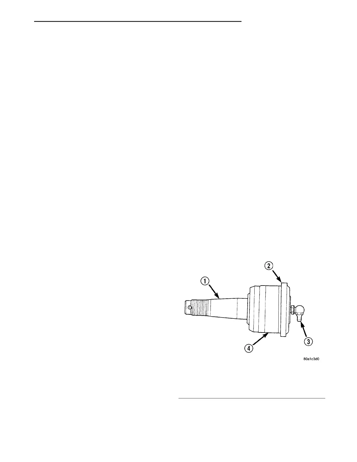
The lower ball joint is pressed into the knuckle and
uses a tapered stud for attachment of the ball joint to
the lower rear control arm (Fig. 11). The tapered
stud of the ball joint is attached to the control arm
using a castle nut and a cotter pin.
Due to the rear knuckle being made of aluminum
and the ball joint being made of steel (dissimilar
metals), corrosion may occur between the pieces. For
this reason, the lower ball joint has a corrosion pre-
ventative coating applied to it. A corrosion prevention
Fig. 11 Lower Ball Joint
1 - TAPERED STUD
2 - CORROSION GASKET INSTALLED HERE
3 - GREASE FITTING
4 - BALL JOINT
ZB REAR SUSPENSION 2 - 35
KNUCKLE (Continued)





 To Next Page