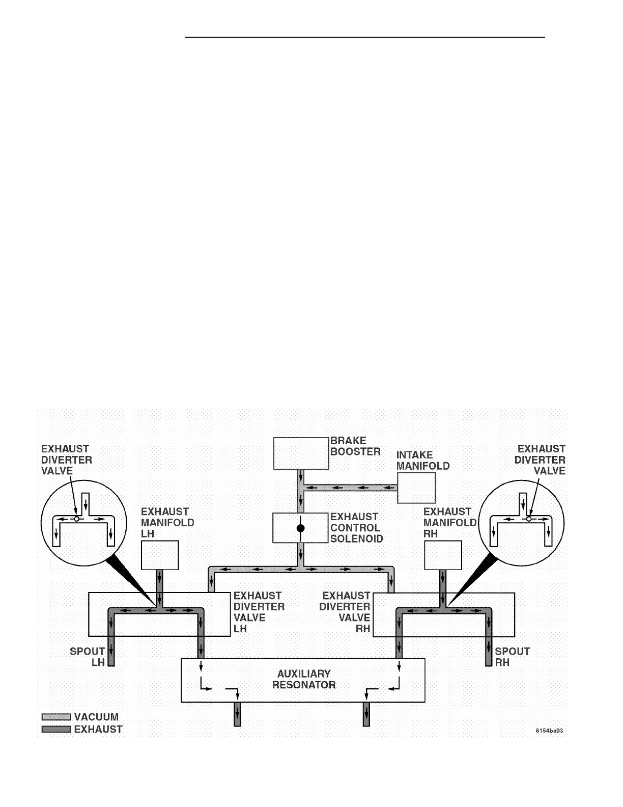
Valves use a butterfly style valve to restrict exhaust
from exiting the side of the vehicle. The diverted
exhaust is then carried to the Auxiliary Resonator
where it is exhausted to the atmosphere (Fig. 1).
The majority of driving conditions will find the
Exhaust Diverter Valves deactivated. During the
deactivation mode, the butterfly valves in the
Diverter Valves are open. During deactivation,
exhaust flow is directed primarily through the side
exhaust pipes. But, there is also a parallel path for
exhaust to flow out to the Auxiliary Resonator. The
deactivation position is also the default position of
the valves, thereby allowing full exhaust flow in the
event of a system failure (Fig. 2).
DIAGNOSIS AND TESTING - EXHAUST SYSTEM
RESTRICTION CHECK
Exhaust system restriction can be checked by mea-
suring back pressure using the DRB IIIt and PEP
module pressure tester.
WARNING: THE NORMAL OPERATING TEMPERA-
TURE OF THE EXHAUST SYSTEM IS VERY HIGH.
THEREFORE, NEVER WORK AROUND OR ATTEMPT
TO SERVICE ANY PART OF THE EXHAUST SYSTEM
UNTIL IT IS COOLED. SPECIAL CARE SHOULD BE
TAKEN WHEN WORKING NEAR THE CATALYTIC
CONVERTER. THE TEMPERATURE OF THE CON-
VERTER RISES TO A HIGH LEVEL AFTER A SHORT
PERIOD OF ENGINE OPERATION TIME.
(1) Disconnect and remove the upstream (before
catalytic converter) oxygen sensor (Refer to 14 -
FUEL SYSTEM/FUEL INJECTION/O2 SENSOR -
REMOVAL).
(2) Install the Exhaust Back Pressure Fitting
Adaptor CH8519.
(3) Connect the Low Pressure Sensor (15 psi)
CH7063 to the back pressure fitting.
(4) Following the PEP module instruction manual,
connect all required cables to the DRB IIIt and PEP
module. Select the available menu options on the
DRBIIIt display screen for using the digital pressure
gauge function.
(5) Apply the park brake and start the engine.
(6) With transmission in Neutral, raise engine
speed to 2000 RPM. Monitor the pressure readings
on the DRBIIIt. Back pressure should not exceed
specified limit. Refer to specification in table below
EXHAUST BACK PRESSURE LIMITS.
NOTE: Repeat test on opposite converter using the
previous steps.
Fig. 1 VACUUM DIAGRAM
(
DEACTIVATED
(
11 - 2 EXHAUST SYSTEM ZB
EXHAUST SYSTEM (Continued)















 To Next Page