(9) Install the shock assembly on the vehicle
(Refer to 2 - SUSPENSION/REAR/SHOCK -
INSTALLATION).
INSTALLATION
NOTE: Functional, it makes no difference which
side of the rear shock clevis bracket is mounted
inboard or outboard on the vehicle. But, to be con-
sistent, it is recommended that the shock assembly
be installed with the lower seat step oriented
inboard.
(1) Position shock assembly in mounting position
as follows:
(a) Insert shock assembly clevis bracket end first
into wheelhouse down though upper control arm
and into open area between lower control arm and
frame.
(b) Raise shock assembly upper eye upward
through access hole just enough to allow lower end
of shock clevis bracket to be shifted outboard over
isolator bushing installed on lower control arm
(Fig. 25).
(c) Lower shock assembly clevis bracket onto iso-
lator bushing and move upper end of shock assem-
bly inboard until the upper eye aligns with its
mounting hole in frame.
(2) Install bolt and nut fastening top of shock
assembly to frame (Fig. 24). Do not tighten at this
time.
(3) Install bolt and nut mounting shock assembly
clevis bracket to isolator bushing on lower control
arm (Fig. 23). Do not tighten at this time.
(4) Install tire and wheel assembly (Refer to 22 -
TIRES/WHEELS - INSTALLATION). Progressively
tighten wheel mounting nuts in proper sequence to
122 N·m (90 ft. lbs.) torque.
(5) Lower vehicle.
(6) Raise carpet up and install shock service plug
(Fig. 22).
(7) Flip convertible top cover down and install tack
strips over mounting studs using care not to pinch
carpet under tack strips (Fig. 21).
(8) Install tack strip mounting nuts (Fig. 21).
Tighten tack strip nuts to 12 N·m (9 ft. lbs.) torque.
(9) Connect rear window defroster electrical con-
nectors.
(10) Inspect and if necessary install new butyl
patches on tack strip support panel to clip joint for
sealing tub area.
(11) Close and latch convertible top and check for
fit.
(12) Verify vehicle fuel tank is full of fuel. If tank
is not full of fuel, reduction in weight will affect
height of vehicle and design height measurement.
(13) Remove any load within passenger and lug-
gage compartments that is not factory equipment.
(14) Position vehicle on alignment rack/drive-on
lift equipped with front turntables and rear slip
plates.
(15) Check all tires for proper inflation pressure
and adjust as necessary.
NOTE: In order to get an accurate rear height mea-
surement it is necessary to remove the belly pan.
(16) Remove belly pan from frame. (Refer to 23 -
BODY/EXTERIOR/BELLY PAN - REMOVAL)
(17) Raise rear of vehicle.
(18) Remove both rear tire and wheel assemblies.
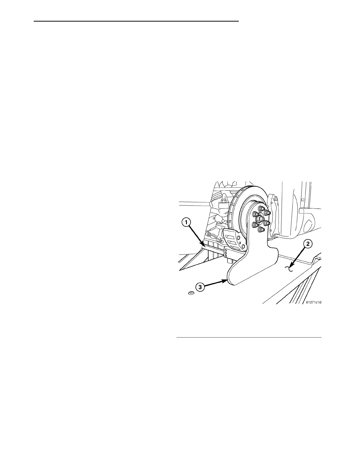
(19) Install Suspension Height Stands, Special
Tool 9096, in place of removed wheels as shown (Fig.
32). Install all wheel mounting nuts and progres-
sively tighten in proper sequence to 122 N·m (90 ft.
lbs.) torque.
(20) Lower vehicle making sure pins are removed
from rear slip plates on alignment rack before Height
Stands make contact.
Fig. 32 Height Stand Mounted On Rear Of Vehicle
1 - SUSPENSION HEIGHT GAGE 6914
2 - SLIP PLATE
3 - SUSPENSION HEIGHT STAND 9096
ZB REAR SUSPENSION 2 - 45
SHOCK ASSEMBLY (Continued)
 Loading...


