NOTE: When setting vehicle to design height while
using Suspension Height Stands it is critically
important to perform the following:
• Make sure locating pins are inserted in correct
wheel diameter holes in Height Stands or measure-
ment will be incorrect. Front wheels use 18 in. posi-
tion hole. Rear wheels use 19 in. position hole (Fig.
33).
• Place ends of Suspension Height Gages, Spe-
cial Tool 6914, right-side-up (same direction as if
mounted against wheels) with notches against
locating pins in ends of Suspension Height Stands
as shown (Fig. 33), otherwise measurements will be
incorrect.
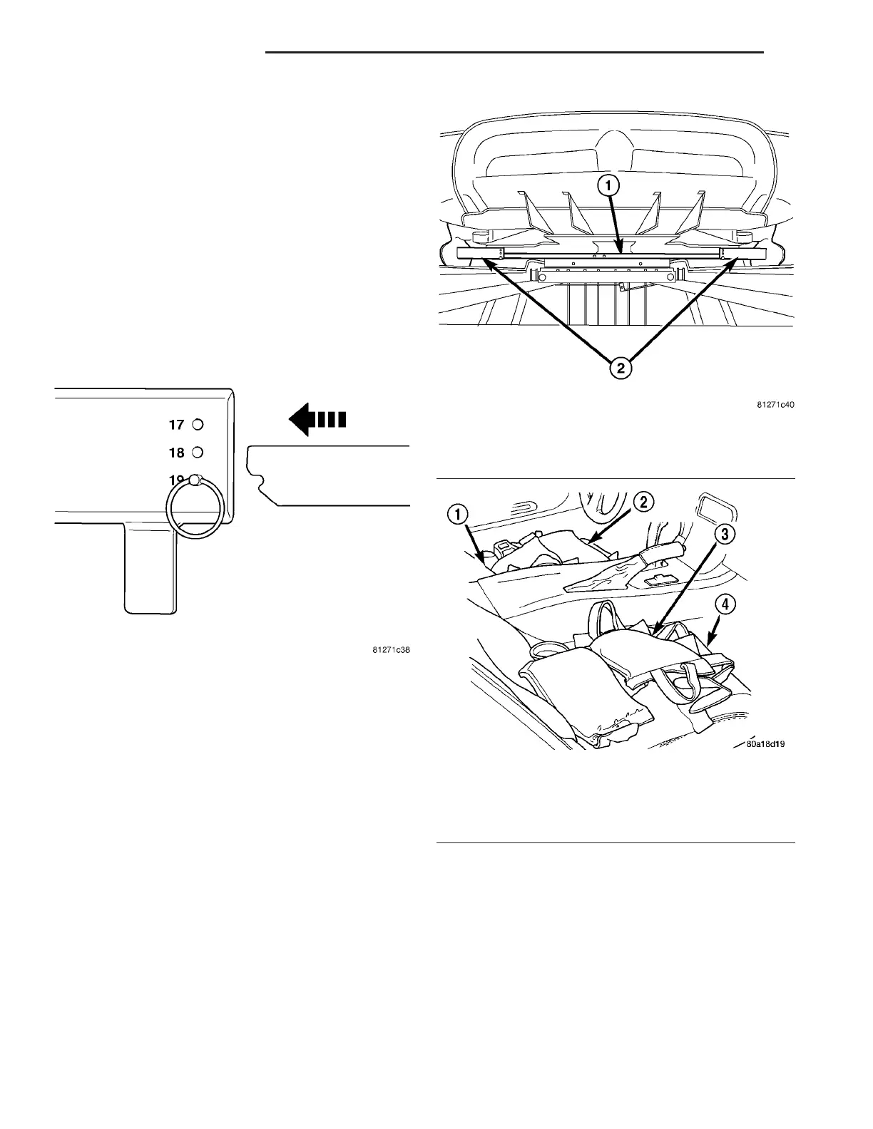
(21) Place Suspension Height Gage, Special Tool
6914, between Suspension Height Stands against
locating pins (Fig. 34). Make sure ends of Gage are
correctly attached to locating pins in Stands (Fig.
33). Refer to above note.
CAUTION: Only apply weight to seat cushions as
described in Step 22. Do not over-ballast the vehi-
cle. If vehicle is over-ballasted, the design height
will be incorrect.
(22) Add 150 pounds ballast weight to each seat
cushion of vehicle (300 pounds total) to lower vehicle
to specified design height (Fig. 35).
(23) Jounce vehicle several times, each time pay-
ing special attention to release vehicle at very bot-
tom of jounce cycle. This is very important in
allowing suspension to settle to correct height.
(24) Measure and record vehicle’s rear design
height. Measure distance between top of Suspension
Height Gage and each frame rail at forward edge of
gage (Fig. 36). This is the nearest point to the Prin-
ciple Locating Point PLP hole.
(25) Compare recorded measurements to specifica-
tions. (Refer to 2 - SUSPENSION/WHEEL ALIGN-
MENT - SPECIFICATIONS)
(26) If recorded height is higher than specifica-
tions, jounce vehicle and remeasure. Before remea-
suring design height, be sure to jounce the
vehicle as described in Step 23. If still above
specifications, one or more rubber bushing mounted
suspension components may not be properly posi-
tioned and tightened. Loosen components as neces-
Fig. 33 Attaching Height Gage To Height Stand
Fig. 34 Height Gage Attached To Height Stands
1 - SUSPENSION HEIGHT GAGE 6914
2 - SUSPENSION HEIGHT STANDS 9096
Fig. 35 Correctly Ballasted Passenger Compartment
1 - DRIVER’S SEAT
2 - BALLAST WEIGHT
3 - BALLAST WEIGHT
4 - PASSENGER’S SEAT
2 - 46 REAR SUSPENSION ZB
SHOCK ASSEMBLY (Continued)
 Loading...


