sary to allow suspension to enter specified design
height, then retighten to specified torque (Refer to 2 -
SUSPENSION/REAR - SPECIFICATIONS). For fur-
ther information, (Refer to 2 - SUSPENSION/
WHEEL ALIGNMENT - STANDARD PROCEDURE -
DESIGN HEIGHT MEASUREMENT).
NOTE: If loosening the lower control arm mounting
bolts is necessary, be sure the alignment adjust-
ment cams do not turn. The cams must stay in their
original position so the alignment of the vehicle is
not affected.
(27) Tighten shock assembly upper mounting bolt
to 136 N·m (100 ft. lbs.) torque.
(28) Tighten shock assembly clevis bracket mount-
ing bolt to 136 N·m (100 ft. lbs.) torque.
(29) Return vehicle to curb height.
(30) Install rear wheelhouse splash shield. (Refer
to 23 - BODY/EXTERIOR/REAR WHEELHOUSE
SPLASH SHIELD - INSTALLATION)
(31) Raise rear of vehicle and remove special tools.
(32) Install tire and wheel assemblies. (Refer to 22
- TIRES/WHEELS - INSTALLATION). Progressively
tighten wheel mounting nuts in proper sequence to
122 N·m (90 ft. lbs.) torque.
(33) Lower vehicle.
STABILIZER BAR
REMOVAL
NOTE: Review all Warnings and Cautions. (Refer to
2 - SUSPENSION - WARNING)
(1) Raise vehicle. (Refer to LUBRICATION &
MAINTENANCE/HOISTING - STANDARD PROCE-
DURE).
(2) Remove both rear wheel and tire assemblies.
(Refer to 22 - TIRES/WHEELS - REMOVAL)
(3) Remove nuts attaching stabilizer bar links to
each end of stabilizer bar.
CAUTION: Use only Remover, Special Tool
MB991113, to remove link from stabilizer bar. Use of
a pickle fork or other alternate tool will damage seal
and ball joint on link.
(4) Separate stabilizer bar from each link using
Remover, Special Tool MB991113.
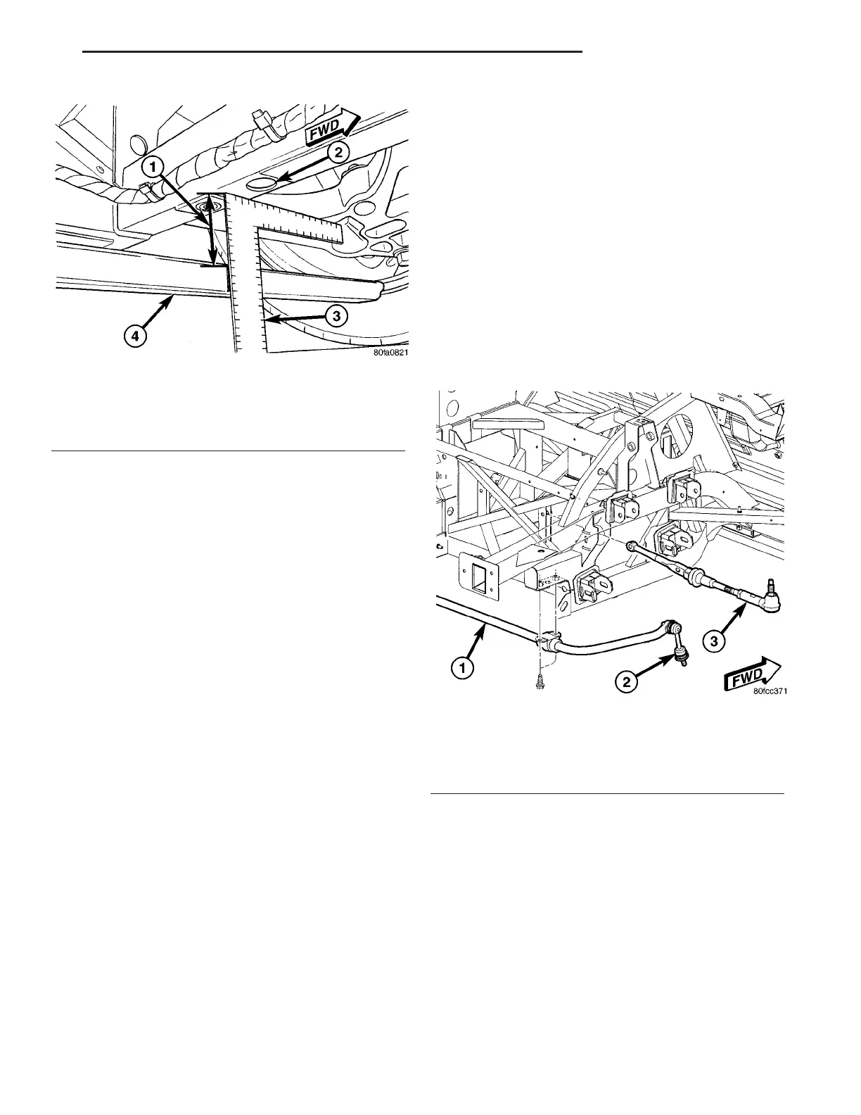
(5) Remove two bolts attaching each stabilizer bar
bushing retainer to frame rails (Fig. 37).
(6) Remove stabilizer bar from vehicle out through
either left or right inner fender area.
(7) To remove bushings:
(a) Slide retainers off bushings.
(b) Remove each bushing from stabilizer bar by
opening slit in bushing and peeling it off bar.
INSTALLATION
(1) Thoroughly clean stabilizer bar in area of bush-
ing contact. Install each NEW bushing on stabilizer
bar by opening slit in bushing and wrapping it
around stabilizer bar, positioning it against retainer
ring on bar.
(2) Slide bushing retainers over bushings.
Fig. 36 Measuring Vehicle Height - Rear Suspension
1 - MEASURE THIS DISTANCE
2 - PLP HOLE
3 - MEASURING DEVICE
4 - HEIGHT GAGE 6914
Fig. 37 Stabilizer Bar And Toe Link Mounting To
Frame
1 - REAR STABILIZER BAR
2 - STABILIZER LINK
3 - TOE LINK
ZB REAR SUSPENSION 2 - 47
SHOCK ASSEMBLY (Continued)
 Loading...


