(3) Install stabilizer bar assembly back into vehicle
in reverse order of removal through wheel opening.
(4) Position bushing retainers against frame rails,
then install four retainer bolts (Fig. 37). DO NOT
TIGHTEN AT THIS TIME.
(5) Install ends of stabilizer bar onto stabilizer bar
link studs. Install attaching nuts. Tighten stabilizer
bar link attaching nuts to 23 N·m (200 in. lbs.)
torque.
(6) Tighten four stabilizer bar bushing retainer
bolts to 91 N·m (67 ft. lbs.) torque.
(7) Install wheel and tire assemblies (Refer to 22 -
TIRES/WHEELS - INSTALLATION). Progressively
tighten wheel mounting nuts in proper sequence to
122 N·m (90 ft. lbs.) torque.
(8) Lower vehicle.
STABILIZER BAR BUSHINGS
REMOVAL
NOTE: Review all Warnings and Cautions. (Refer to
2 - SUSPENSION - WARNING)
(1) Raise vehicle. (Refer to LUBRICATION &
MAINTENANCE/HOISTING - STANDARD PROCE-
DURE).
(2) Remove both rear wheel and tire assemblies.
(Refer to 22 - TIRES/WHEELS - REMOVAL)
(3) Remove two bolts attaching each stabilizer bar
bushing retainer to frame rails (Fig. 37).
(4) Slide retainers off bushings.
(5) Remove each bushing from stabilizer bar by
opening slit in bushing and peeling it off bar.
INSTALLATION
(1) Thoroughly clean stabilizer bar in area of bush-
ing contact. Install each NEW bushing on stabilizer
bar by opening slit in bushing and wrapping it
around stabilizer bar, positioning it against retainer
ring on bar.
(2) Slide bushing retainers over bushings.
(3) Position bushing retainers against frame rails,
then install four retainer bolts (Fig. 37). Tighten four
stabilizer bar bushing retainer bolts to 91 N·m (67 ft.
lbs.) torque.
(4) Install wheel and tire assemblies (Refer to 22 -
TIRES/WHEELS - INSTALLATION). Progressively
tighten wheel mounting nuts in proper sequence to
122 N·m (90 ft. lbs.) torque.
(5) Lower vehicle.
STABILIZER LINK
REMOVAL
NOTE: Review all Warnings and Cautions. (Refer to
2 - SUSPENSION - WARNING)
(1) Raise vehicle. (Refer to LUBRICATION &
MAINTENANCE/HOISTING - STANDARD PROCE-
DURE).
(2) Remove wheel and tire assembly. (Refer to 22 -
TIRES/WHEELS - REMOVAL)
(3) Remove nut attaching stabilizer link to end of
stabilizer bar.
CAUTION: Use only Remover, Special Tool
MB991113, to remove link from stabilizer bar. Use of
a pickle fork or other alternate tool will damage seal
and ball joint on link.
(4) Separate stabilizer bar from link using
Remover, Special Tool MB991113.
(5) Loosen, but do not remove, nut attaching stabi-
lizer link to lower control arm (Fig. 38). Thread nut
to end of stabilizer bar link stud.
CAUTION: The nut must be positioned at the end of
the stabilizer link stud when removing the link from
the lower control arm. This will prevent the end of
the stud from being damaged when removing it
from the lower control arm as described in the fol-
lowing steps.
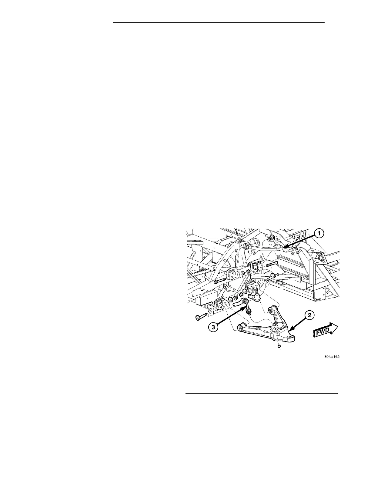
Fig. 38 Upper And Lower Control Arms
1 - UPPER CONTROL ARM
2 - LOWER CONTROL ARM
3 - STABILIZER LINK
2 - 48 REAR SUSPENSION ZB
STABILIZER BAR (Continued)
 Loading...


