(6) Position center punch in dimple on end of link
stud (Fig. 39).
(7) Strike center punch with hammer to remove
link stud from lower control arm.
(8) Remove stabilizer link from vehicle.
INSTALLATION
(1) Insert stabilizer link stud into mounting hole
in lower control arm (Fig. 38). Install stabilizer link
nut and tighten to 23 N·m (17 ft. lbs.) torque.
(2) Install stud of opposite end of stabilizer link
into stabilizer bar mounting hole. Install link nut
and tighten to 23 N·m (17 ft. lbs.) torque.
(3) Install wheel and tire assembly (Refer to 22 -
TIRES/WHEELS - INSTALLATION). Progressively
tighten wheel mounting nuts in proper sequence to
122 N·m (90 ft. lbs.) torque.
(4) Lower vehicle.
TOE LINK
DESCRIPTION
The rear suspension toe link is similar to steering
gear tie rod linkage (Fig. 40). It has an outer tie rod,
jam nut and flexible jointed link that attaches it to
the frame of the vehicle. The outer tie rod attaches it
to the rear knuckle.
OPERATION
The rear suspension toe link is similar in function
to the steering gear tie rod linkage. It controls the
steering attitude of the rear wheels. It is used to set
rear wheel static toe position (basic toe-in and toe-
out). It can also be adjusted up or down changing
dynamic toe. (Refer to 2 - SUSPENSION/WHEEL
ALIGNMENT - STANDARD PROCEDURE).
REMOVAL
NOTE: Review all Warnings and Cautions. (Refer to
2 - SUSPENSION - WARNING).
(1) Raise vehicle. (Refer to LUBRICATION &
MAINTENANCE/HOISTING - STANDARD PROCE-
DURE)
(2) Remove wheel and tire assembly. (Refer to 22 -
TIRES/WHEELS - REMOVAL)
(3) Remove plastic appearance cap from toe link
stud.
(4) Remove nut from toe link at knuckle (Fig. 41).
CAUTION: When releasing toe link from knuckle
using Puller, Special Tool C-4150A, use care not to
pinch and damage grease seal.
(5) Release toe link from knuckle using Puller,
Special Tool C-4150A (Fig. 42). Remove tool.
NOTE: The toe link to frame outer mounting loca-
tion is used for adjusting the rear wheel dynamic
toe pattern. The dynamic rear wheel toe pattern is
adjusted by installing an adjustment shim at this
location. Be sure when removing the outer mount-
ing bolt and nut that the adjustment shim is not dis-
carded. Also, note the side of the vehicle and the
position that the adjustment shim was installed. It
must be reinstalled in the same position to maintain
the rear wheel dynamic toe pattern once toe link
installation is complete.
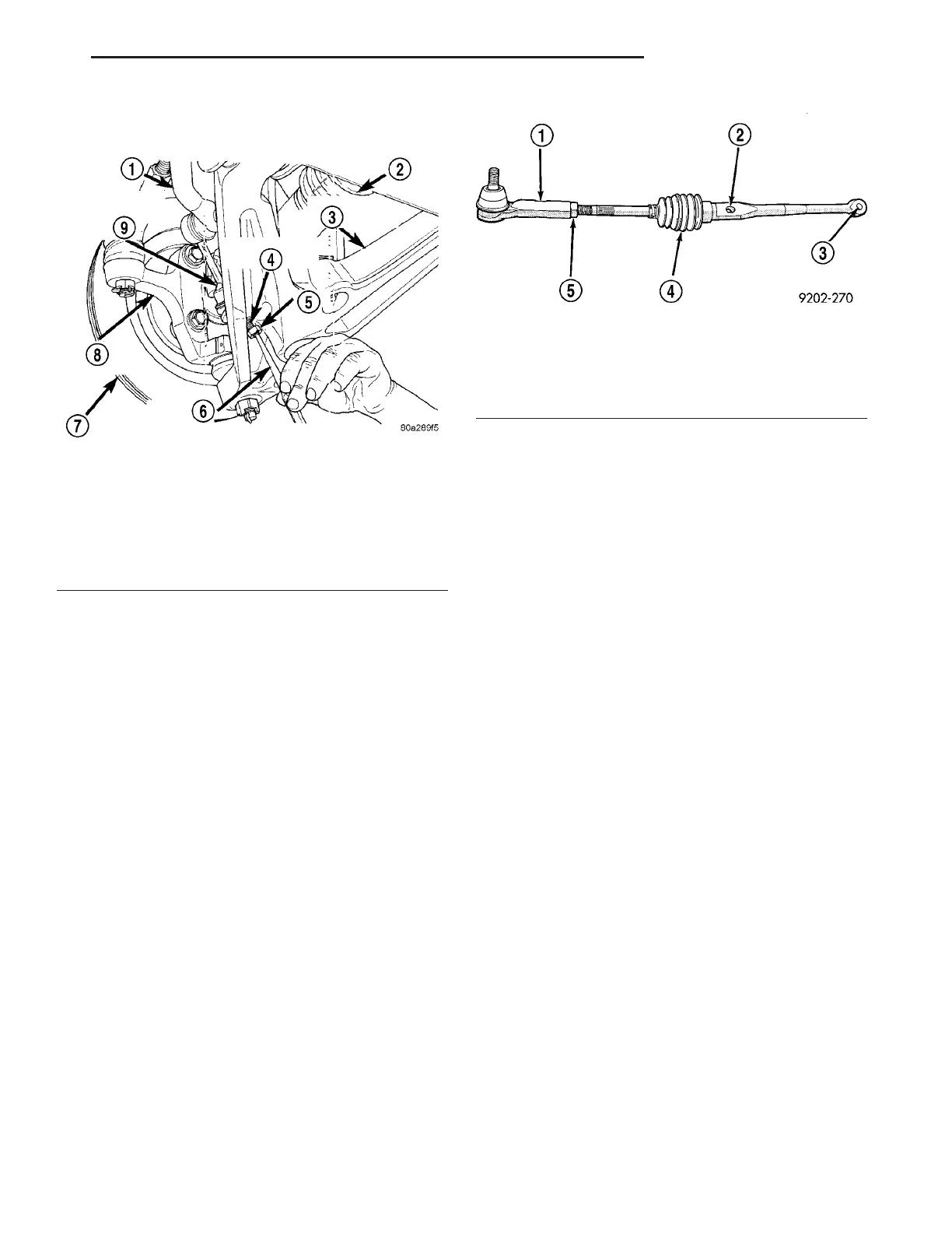
Fig. 39 Stabilizer Link Removal
1 - STABILIZER BAR
2 - HALFSHAFT
3 - LOWER CONTROL ARM
4 - STABILIZER LINK STUD
5 - NUT
6 - CENTER PUNCH
7 - BRAKE ROTOR
8 - KNUCKLE
9 - STABILIZER LINK
Fig. 40 Rear Toe Link Assembly
1 - OUTER TIE ROD
2 - TOE PATTERN ADJUSTMENT HOLE
3 - MOUNTING HOLE
4 - FLEX JOINT BOOT
5 - JAM NUT
ZB REAR SUSPENSION 2 - 49
STABILIZER LINK (Continued)
 Loading...


