WELDING
PROCESS
FLUX
CORED
ARC
GAS
METAL
ARC
(MIG)*
SHIELDED
METAL
ARC
(STICK)
Direction
of Welding
Vertical Vertical
Down Hill
(only)
Vertical
Down Hill
(only)
Vertical -
Up Hill
(only)
Flat &
Overhead
Flat -
Push or
Drag
Flat -
Push or
Drag
Flat - Drag
*First choice - Gas Metal Arc Welding Process:
Butt joints - apply two layers (passes) of weld metal.
First pass should only fill approximately
1
⁄
2
the thick-
ness. Vertical position welds - maintain electrode wire
at leading edge of weld puddle while traveling down
hill to produce maximum penetration into the sleeve.
These techniques work for FCAW as well.
**E7018 new electrodes may be exposed to the atmo-
sphere for up to ten hours with no harmful effect.
Reconditioning schedules should come from the man-
ufacturer.
REAR TRANSMISSION
CROSSMEMBER
REMOVAL
(1) Raise and support the vehicle. (Refer to
LUBRICATION & MAINTENANCE/HOISTING -
STANDARD PROCEDURE)
(2) Remove the belly pan. (Refer to 23 - BODY/EX-
TERIOR/BELLY PAN - REMOVAL)
(3) Remove the transmission mount nut. (Fig. 24)
(4) Loosen the crossmember slide nuts.
(5) Remove the crossmember side bolts.
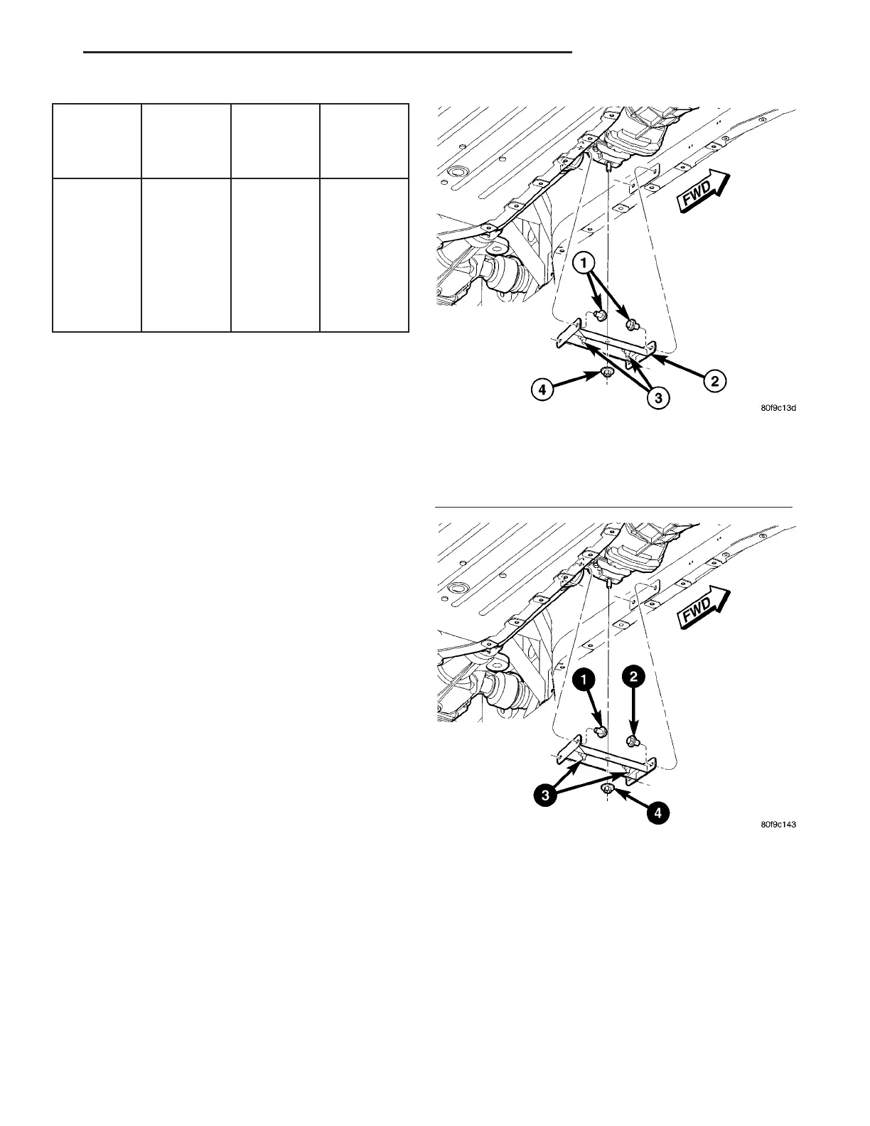
INSTALLATION
(1) Install the crossmember and install the side
bolts.
(2) Tighten the side bolts to 61 N·m (45 ft. lbs.)
using the sequence shown. (Fig. 25)
(3) Tighten the slide nuts to 61 N·m (45 ft. lbs.).
(4) Install and tighten the transmission mount nut
to 61 N·m (45 ft. lbs.).
(5) Install the belly pan. (Refer to 23 - BODY/EX-
TERIOR/BELLY PAN - INSTALLATION)
Fig. 24 TRANSMISSION CROSSMEMBER
1 - SIDE BOLTS (2 PER SIDE)
2 - CROSSMEMBER
3 - SLIDE NUTS
4 - TRANSMISSION MOUNT NUT
Fig. 25 TRANSMISSION CROSSMEMBER
TIGHTENING SEQUENCE
ZB FRAME & BUMPERS 13 - 21
FRAME (Continued)
 Loading...


