CRANKSHAFT POSITION
SENSOR
DESCRIPTION
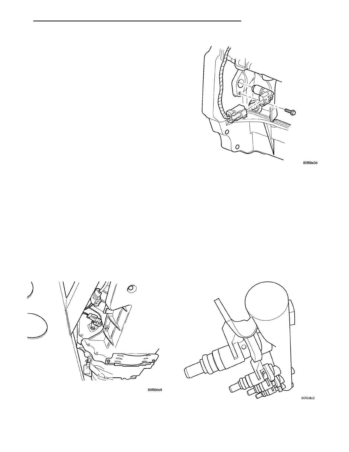
The crankshaft position sensor is located in the
passengers side of the engine block, below the
exhaust manifold at the rear of the engine (Fig. 1).
OPERATION
There are 5 sets of slots on flywheel ring gear.
Each set contains 2 slots, for a total of 10 slots. Basic
timing is determined by the position of the last slot
in each group. Once the Powertrain Control Module
(PCM) senses the last slot, it determines crankshaft
position (which piston will be next at TDC) from the
camshaft position sensor input. It may take the PCM
up to one engine revolution to determine crankshaft
position during cranking.
The PCM uses the camshaft position sensor to
determine injector sequence. Once crankshaft posi-
tion has been determined, the PCM begins energizing
the injectors in sequence. The PCM determines igni-
tion timing from the crankshaft timing sensor.
REMOVAL
The sensor is located at the rear lower passenger
side of motor (Fig. 1).
(1) Disconnect electrical connector from crankshaft
position sensor (Fig. 2).
(2) Remove sensor mounting bolt.
(3) Pull sensor out. A light tap to top of sensor
may ease removal.
INSTALLATION
(1) Slide the sensor into the hole.
(2) Install and tighten the mounting bolt to 11
N·m (95 in. lbs.) torque.
(3) Connect the electrical connector to the sensor
and lock.
FUEL INJECTORS
DESCRIPTION
The fuel injectors are electrical solenoids (Fig. 3).
The injectors are positioned in the intake manifold
with the nozzle ends directly above the intake valve
port.
Fig. 1 CRANKSHAFT POSITION SENSOR
Fig. 2 CRANKSHAFT POSITION SENSOR
ASSEMBLY
Fig. 3 FUEL INJECTOR & CLIP
ZB FUEL INJECTION 14 - 31















 To Next Page