OPERATION
The injector contains a pintle that closes off an ori-
fice at the nozzle end. When electric current is sup-
plied to the injector, the armature and needle move a
short distance against a spring, allowing fuel to flow
out the orifice. Because the fuel is under high pres-
sure, a fine spray is developed in the shape of a hol-
low cone. The spraying action atomizes the fuel,
adding it to the air entering the combustion chamber.
The injectors are positioned in the intake manifold.
REMOVAL
(1) Release fuel system pressure. Refer to Fuel
Pressure Release Procedure in this section.
(2) Remove the battery cover and disconnect nega-
tive battery cable.
(3) Remove the air cleaner assembly, refer to the
Engine/Air Intake System/Air Cleaner Housing for
more information.
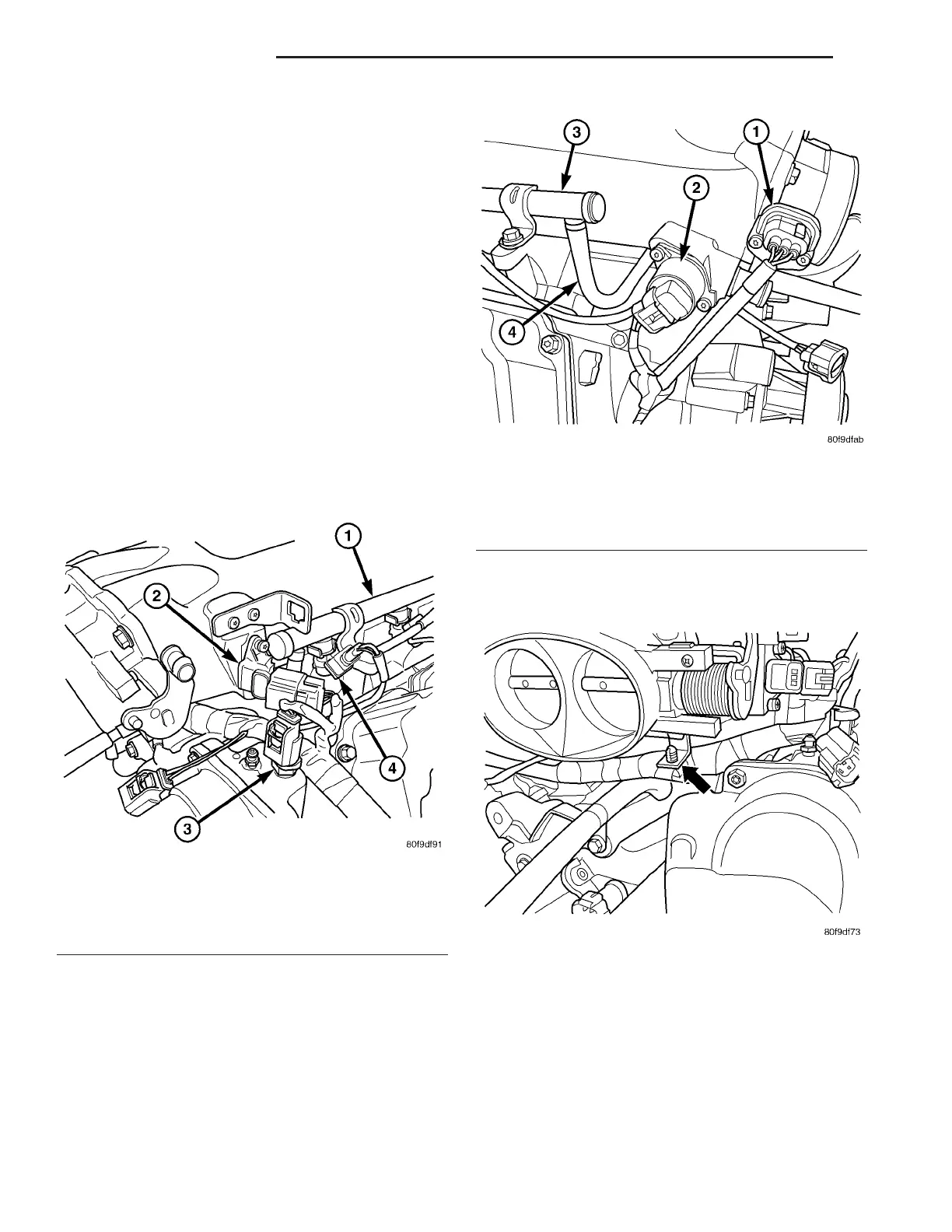
(4) Disconnect the electrical connector to the MAP
sensor and Coolant Temperature sensor (Fig. 4).
(5) Disconnect the electrical connector to the TPS
and Idle Air Control (Fig. 5).
(6) Remove the wiring harness from the wiring
clips under thew throttle body (Fig. 6).
Fig. 4 MAP & COOLANT TEMP. SENSOR
1 - Fuel Rail
2 - MAP Sensor
3 - Coolant Temperature Sensor
4 - Fuel Injector
Fig. 5 TPS & IDLE AIR CONTROL
1 - Throttle Position Sensor
2 - Idle Air Control Motor
3 - Fuel Rail
4 - Connector Fuel Line for Fuel Rails
Fig. 6 WIRING CLIP
14 - 32 FUEL INJECTION ZB
FUEL INJECTORS (Continued)















 To Next Page