(1) Clamp upper control arm securely in vise so
that bushing to be removed is closest to vise jaws
(Fig. 48).
NOTE: Before using Special Tool 6969B, lubricate
threads of Screw Assembly 6969-3 with appropriate
lubricant.
(2) Assemble pieces of Remover, Special Tool
6969B, through bushing as shown (Fig. 49).
CAUTION: Do not use any type of impact wrench on
Special Tool 6969B. Use only hand tools.
(3) Hold Screw, Special Tool 6969-3, stationary
while rotating Nut, Special Tool 6969-4 clockwise.
This action will force isolator bushing out of control
arm, into Receiver, Special Tool 6969-2.
(4) Remove tools and bushing from arm. A small
portion of bushing rubber may come loose lodging
itself between Remover and control arm bushing
boar, causing some resistance during tool removal.
NOTE: For bushing installation, (Refer to 2 - SUS-
PENSION/FRONT/UPPER CONTROL ARM - ASSEM-
BLY).
INSPECTION - UPPER CONTROL ARM
Inspect the upper control arm for the following:
• Inspect the control arm for any signs of damage
and cracks. If the control arm shows any sign of
damage or cracks, the control arm must be replaced.
Do not attempt to repair or straighten a broken or
bent control arm.
• Inspect both control arm isolator bushings for
severe deterioration. These bushings can be serviced
separately.
• Inspect the ball joint per the procedure in this
section of the service manual.
• Inspect the ball joint grease seal (boot) for cuts
or splits. It can be serviced separately.
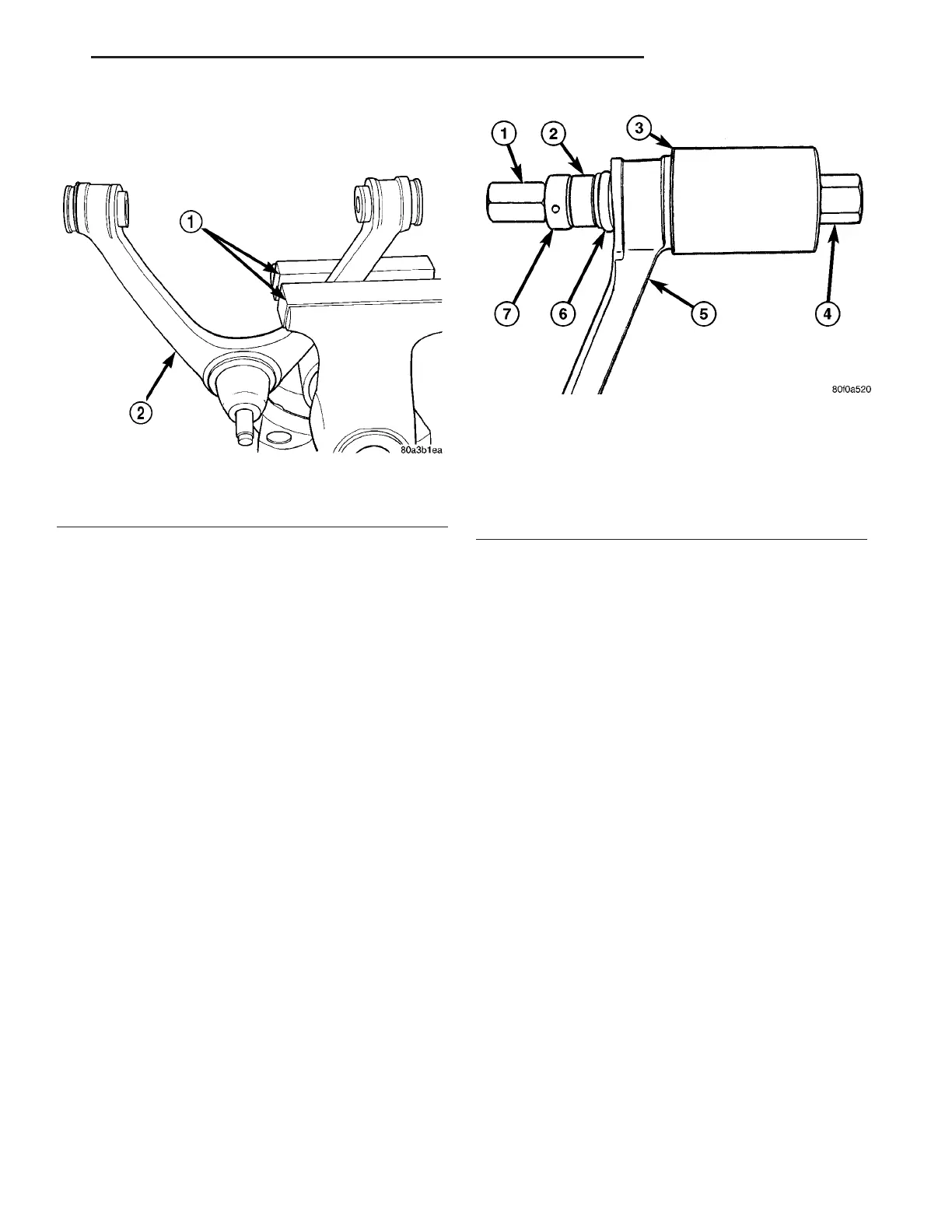
Fig. 48 Control Arm Mounted In Vise
1 - SOFT JAW VISE CAPS
2 - CONTROL ARM
Fig. 49 Tool 6969B Installed For Bushing Removal
1 - DOUBLE THREADED NUT 6969-4
2 - SPACER 6969-1
3 - RECEIVER 6969-2
4 - SCREW ASSEMBLY 6969-3
5 - CONTROL ARM
6 - BUSHING
7 - BEARING
ZB REAR SUSPENSION 2 - 53
UPPER CONTROL ARM (Continued)
 Loading...


