ASSEMBLY - ISOLATOR BUSHINGS
NOTE: The following procedure can be used for
either upper control arm isolator bushing.
(1) Squarely position isolator bushing into control
arm pivot end bore from outboard side.
NOTE: Before using Special Tool 6969B, lubricate
threads of Screw Assembly 6969-3 with appropriate
lubricant.
(2) Assemble pieces of Remover, Special Tool
6969B, through bushing and arm as shown (Fig. 50).
CAUTION: Do not use any type of impact wrench on
Special Tool 6969B. Use only hand tools.
(3) Hold Screw, Special Tool 6969-3, stationary
while rotating Nut, Special Tool 6969-4 clockwise.
This action will draw isolator bushing into control
arm.
(4) Continue to rotate Nut until bushing metal
flange squarely contacts control arm. Do not over-
tighten Screw.
(5) Remove tools.
(6) Install upper control arm on vehicle. (Refer to 2
- SUSPENSION/REAR/UPPER CONTROL ARM -
INSTALLATION)
INSTALLATION
Attach the upper control arm to the knuckle, then
install the parts together on the vehicle. (Refer to 2 -
SUSPENSION/REAR/KNUCKLE - INSTALLATION)
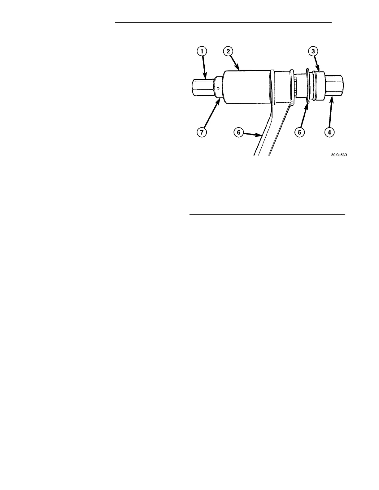
Fig. 50 Tool 6969B Installed For Bushing Installation
1 - DOUBLE THREADED NUT 6969-4
2 - CUP 6969-7
3 - INSTALLER 6969-8
4 - SCREW ASSEMBLY 6969-3
5 - NEW BUSHING
6 - CONTROL ARM
7 - BEARING
2 - 54 REAR SUSPENSION ZB
UPPER CONTROL ARM (Continued)
 Loading...


