(23) Verify tilt mechanism operates properly.
(24) Road test vehicle to ensure proper operation
of steering.
SPECIFICATIONS
STEERING COLUMN FASTENER TORQUE
DESCRIPTION N·m
Ft.
Lbs.
In.
Lbs.
Driver Airbag Mounting
Screws
12 — 105
Intermediate Shaft Pinch
Bolts
49 36 —
Intermediate Shaft
Extension Pinch Bolt
49 36 —
Intermediate Shaft
Extension Bearing Mounting
Bolts
17 — 150
Steering Column Mounting
Nuts
17 — 150
Steering Wheel Retaining
Bolt
54 40 —
IGNITION SWITCH
REMOVAL
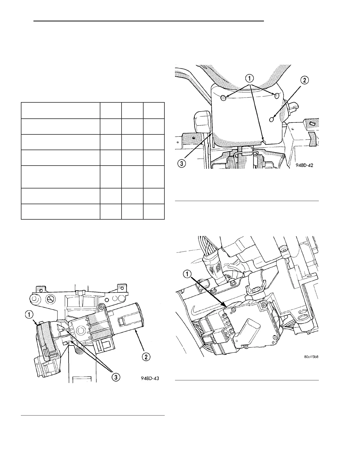
The ignition switch attaches to the lock cylinder
housing on the end opposite the lock cylinder (Fig. 9).
For ignition switch terminal and circuit identifica-
tion, refer to the Wiring Diagrams sections.
(1) Disconnect negative cable from battery.
(2) Place key cylinder in RUN position. Through
the hole in the lower shroud, depress lock cylinder
retaining tab and remove key cylinder (Fig. 10).
(3) Remove upper and lower shrouds from steering
column.
(4) Disconnect electrical connectors from ignition
switch (Fig. 11).
(5) Remove the 2 screws on the top of the multi-
function switch and relocate (Fig. 12).
(6) Remove ignition switch mounting screw (Fig.
13) with a #10 Torxt bit.
(7) Pull ignition switch from steering column (Fig.
14).
Fig. 9 Ignition Switch—Viewed From Below Column
1 - IGNITION SWITCH
2 - LOCK CYLINDER HOUSING
3 - RETAINING TABS
Fig. 10 Steering Column Shrouds
1 - SCREW ACCESS HOLE
2 - TAB ACCESS HOLE
3 - LOWER SHROUD
Fig. 11 Ignition Switch
1 - IGNITION SWITCH
ZB COLUMN 19 - 15
COLUMN (Continued)













 To Next Page