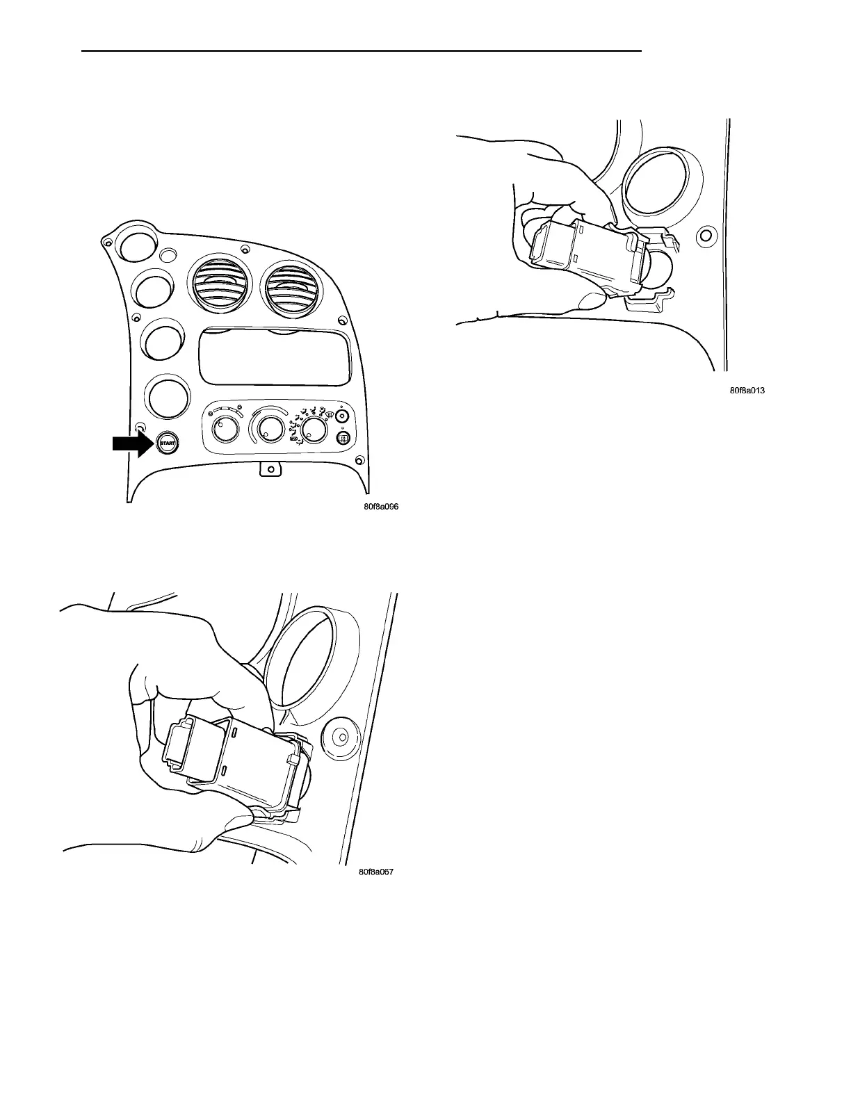
START BUTTON
REMOVAL
(1) Remove the center bezel (Fig. 16) (Refer to 23 -
BODY/INSTRUMENT PANEL/INSTRUMENT
PANEL CENTER BEZEL - REMOVAL).
(2) Squeeze the tabs on the switch (Fig. 17).
(3) Remove the switch (Fig. 18).
INSTALLATION
(1) Install switch into center bezel (Fig. 18).
(2) Install the center bezel (Fig. 16) (Refer to 23 -
BODY/INSTRUMENT PANEL/INSTRUMENT
PANEL CENTER BEZEL - INSTALLATION).
INTERMEDIATE SHAFT
DIAGNOSIS AND TESTING - STEERING
COLUMN INTERMEDIATE SHAFT
The steering column intermediate shaft and its
flexible universal joints must be inspected whenever
any of the following conditions exist.
• After the vehicle has been involved in a collision
which deploys the airbag, regardless of the extent of
damage to the vehicle.
• After the vehicle has been involved in an under-
carriage impact which results in any type of damage
or bending of front suspension components or the
frame of the vehicle.
• Under any conditions which result in the steer-
ing gear, steering column or steering column shaft
receiving a force great enough to move the steering
column or shaft forward or rearward in the vehicle.
Inspect the intermediate shaft and its flexible
joints for any of the following conditions:
• Seized or binding bearings
• Loose bearing stakes
• Bearings not fully seated
• Shaft bent
Upon inspection, if any of the above conditions
exist, replacement of the entire steering column
intermediate shaft is necessary.
REMOVAL
NOTE: Review all Warnings and Cautions. (Refer to
19 - STEERING - WARNING).
(1) Disconnect negative (-) cable from battery and
isolate cable.
Fig. 16 START BUTTON LOCATION
Fig. 17 START BUTTON CLIPS
Fig. 18 START BUTTON REMOVED
ZB COLUMN 19 - 17









 To Next Page