(4) Slide original size toe shims onto mounting
bolts between gear and frame mounts (Fig. 2).
Tighten steering gear mounting bolts to 203 N·m
(150 ft. lbs) torque.
(5) Raise vehicle.
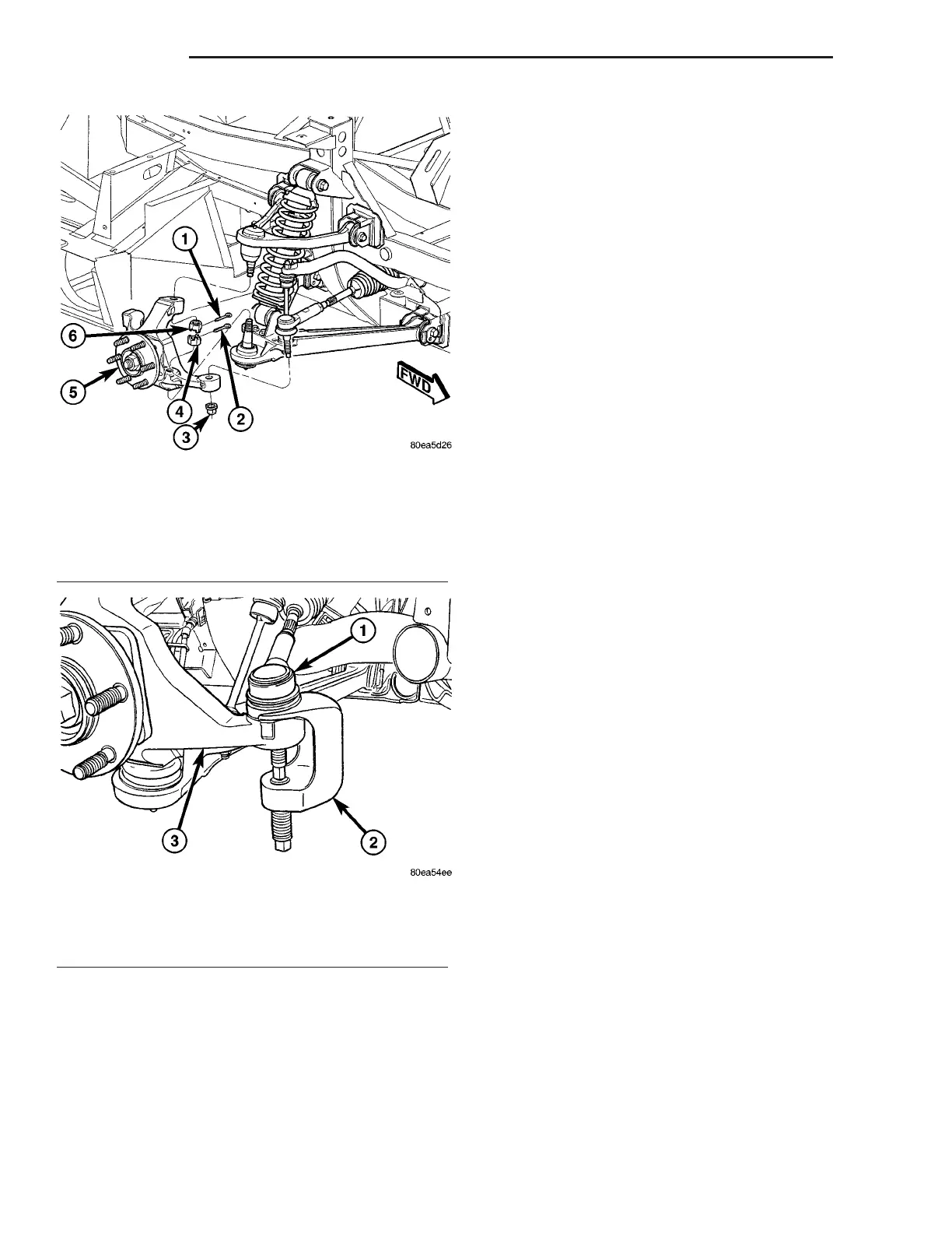
(6) Install outer tie rods onto steering knuckles
(Fig. 3). Install NEW tie rod nuts. Tighten nuts to 75
N·m (55 ft. lbs.) torque.
(7) Install wheels and tires (Refer to 22 - TIRES/
WHEELS - INSTALLATION). Progressively tighten
wheel mounting nuts in proper sequence to 122 N·m
(90 ft. lbs.) torque.
(8) Lower vehicle.
(9) Install power steering pressure hose and return
hose in steering gear fluid ports. Tighten hose tube
nuts to 28 N·m (21 ft. lbs.) torque.
(10) Align intermediate shaft with steering gear
shaft. Slide intermediate shaft coupling onto steering
gear shaft until bolt hole is properly aligned. It may
be necessary to use a soft (brass) drift and hammer
to tap the coupling into place.
(11) Install coupling pinch bolt (Fig. 1). Tighten
pinch bolt to 49 N·m (36 ft. lbs.) torque.
(12) Install air cleaner housing. (Refer to 9 -
ENGINE/AIR INTAKE SYSTEM/AIR CLEANER
HOUSING - INSTALLATION)
(13) Remove steering wheel holder.
(14) Connect battery (-) negative cable to battery
negative post.
CAUTION: Do not use automatic transmission fluid
in power steering system. Only use MoparT Power
Steering Fluid or equivalent.
(15) Fill power steering pump reservoir to correct
fluid level. (Refer to 19 - STEERING/PUMP/FLUID -
STANDARD PROCEDURE)
(16) Perform Power Steering Pump Initial Opera-
tion procedure. (Refer to 19 - STEERING/PUMP -
STANDARD PROCEDURE)
(17) Check for leaks at all hose connections.
(18) Check wheel alignment and adjust toe as nec-
essary. (Refer to 2 - SUSPENSION/WHEEL ALIGN-
MENT - STANDARD PROCEDURE)
TIE ROD - OUTER
REMOVAL
NOTE: Review all Warnings and Cautions. (Refer to
19 - STEERING - WARNING).
(1) Raise vehicle. (Refer to LUBRICATION &
MAINTENANCE/HOISTING - STANDARD PROCE-
DURE).
(2) Remove front wheel and tire assembly. (Refer
to 22 - TIRES/WHEELS - REMOVAL).
(3) Loosen inner-to-outer tie rod adjuster jam nut
(Fig. 5).
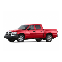
CAUTION: When releasing tie rod from knuckle
using Puller, Special Tool C-4150A, use care not to
pinch and damage tie rod grease seal.
(4) Remove nut from outer tie rod (Fig. 3).
Fig. 3 Knuckle Mounting
1 - UPPER BALL JOINT COTTER PIN
2 - LOWER BALL JOINT COTTER PIN
3 - TIE ROD NUT
4 - LOWER BALL JOINT NUT
5 - KNUCKLE (WITH HUB AND BEARING)
6 - UPPER BALL JOINT NUT
Fig. 4 Puller Positioned To Release Tie Rod
1 - OUTER TIE ROD
2 - PULLER C-4150A
3 - KNUCKLE
19 - 24 GEAR ZB
GEAR (Continued)












 To Next Page