(5) Release outer tie rod from knuckle using
Puller, Special Tool C-4150A (Fig. 4). Remove tool.
(6) Remove outer tie rod by unthreading it from
inner tie rod.
INSTALLATION
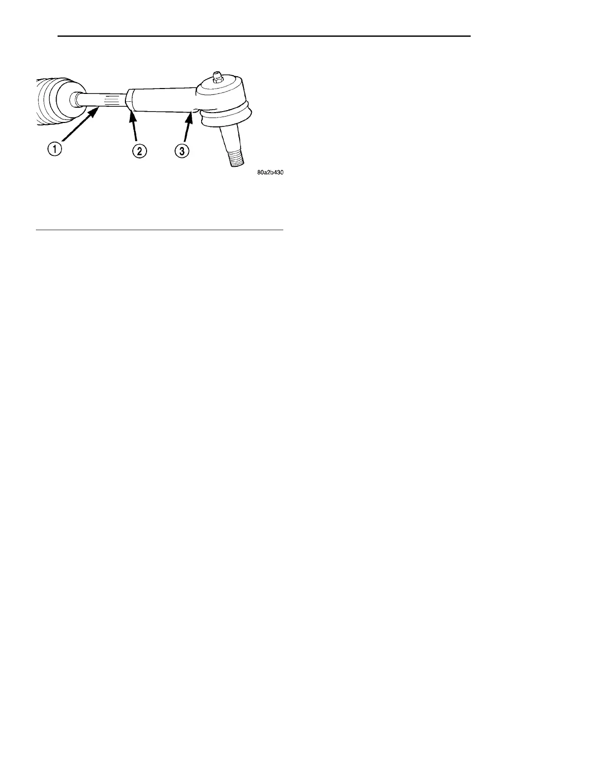
NOTE: Before installing outer tie rod end on inner
tie rod, be sure jam nut is on inner tie rod (Fig. 5).
(1) Thread outer tie rod onto inner tie rod. Snug
inner-to-outer tie rod adjuster jam nut (Fig. 5). Do
not torque jam nut until wheel alignment toe has
been set.
(2) Install outer tie rod onto steering knuckle (Fig.
3). Install NEW tie rod nut. Tighten nut to 75 N·m
(55 ft. lbs.) torque.
(3) Install wheels and tire assembly (Refer to 22 -
TIRES/WHEELS - INSTALLATION). Progressively
tighten wheel mounting nuts in proper sequence to
122 N·m (90 ft. lbs.) torque.
(4) Lower vehicle.
(5) Check wheel alignment and adjust toe as nec-
essary. (Refer to 2 - SUSPENSION/WHEEL ALIGN-
MENT - STANDARD PROCEDURE)
Fig. 5 Tie Rod Jam Nut (Typical)
1 - INNER TIE ROD
2 - JAM NUT
3 - OUTER TIE ROD
ZB GEAR 19 - 25
TIE ROD - OUTER (Continued)











 To Next Page