• Smooth power assist
• Noiseless operation
• Proper fluid level
• No system leaks
• Proper fluid condition
(18) Stop the engine. If all the proper conditions
exist, the procedure is complete.
REMOVAL
NOTE: Review all Warnings and Cautions. (Refer to
19 - STEERING - WARNING).
CAUTION: Cap all open ends of power steering
hoses, power steering pump fittings and steering
gear ports when disconnected. This will prevent the
entry of foreign material into the components dur-
ing servicing.
(1) Disconnect negative (-) cable from battery and
isolate cable.
(2) Remove air cleaner housing. (Refer to 9 -
ENGINE/AIR INTAKE SYSTEM/AIR CLEANER
HOUSING - REMOVAL)
(3) Siphon power steering fluid from fluid reser-
voir.
(4) Remove accessory drive belt from tensioner
pulley and power steering pump drive pulley. (Refer
to 7 - COOLING/ACCESSORY DRIVE/DRIVE
BELTS - REMOVAL)
(5) Unthread quick-connect fitting and remove
power steering pressure hose from power steering
pump pressure fitting (Fig. 7). Drain excess power
steering fluid from line.
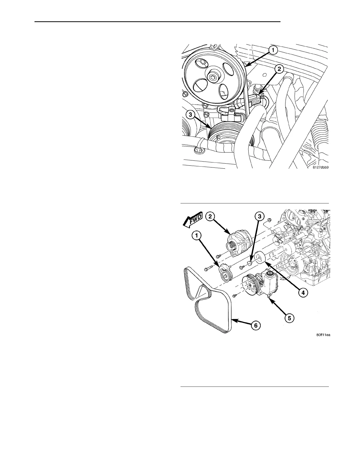
(6) Disconnect A/C clutch coil wire connector (Fig.
1).
(7) Remove return hose from radiator fan at power
steering pump reservoir (Fig. 7).
(8) Remove return hose from fluid cooler at power
steering pump reservoir (Fig. 7).
(9) Remove three bolts mounting power steering
pump to engine (Fig. 2).
(10) Remove power steering pump.
(11) If required, transfer necessary parts from
removed power steering pump to replacement power
steering pump. (Refer to 19 - STEERING/PUMP -
DISASSEMBLY)
DISASSEMBLY - PUMP PULLEY
CAUTION: Do not reuse the old power steering
pump pulley; it is not intended for reuse. A new pul-
ley must be installed if removed.
(1) Remove power steering pump assembly. (Refer
to 19 - STEERING/PUMP - REMOVAL)
(2) Remove pulley from pump with an appropriate
power steering pulley removal tool (Fig. 3).
Fig. 1 A/C Wiring Connector Below Pump
1 - POWER STEERING PUMP PULLEY
2 - A/C CLUTCH COIL WIRING CONNECTOR
3 - A/C CLUTCH PULLEY
Fig. 2 Belt Driven Components Mounting
1 - BELT TENSIONER
2 - GENERATOR
3 - SPACER
4 - IDLER PULLEY
5 - POWER STEERING PUMP
6 - BELT
ZB PUMP 19 - 27
PUMP (Continued)







 To Next Page