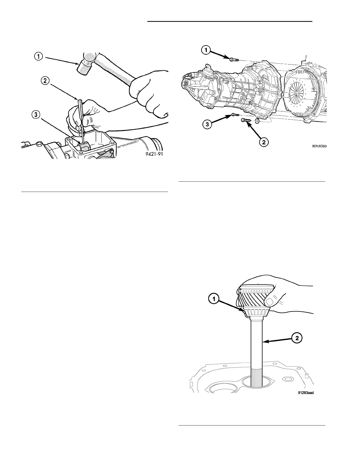
(39) Install offset lever roll pin (Fig. 110).
(40) Install Mopart Gasket Maker to the shift
cover sealing surface and position cover on the trans-
mission.
(41) Install shift cover four mounting bolts and
tighten to 18 N·m (13 ft. lbs.).
INSTALLATION
(1) Slide transmission back into the clutch and
seat against the bell housing.
(2) Install transmission bolts (Fig. 111) and tighten
bolts to:
• Transmission to top of engine - 41 N·m (30 ft.
lbs.)
• 7/16 Transmission bolts - 68 N·m (50 ft. lbs.)
• Transmission to oil pan - 23 N·m (200 in. lbs.)
(3) Connect the transmission harness connector.
(4) Install the isolator/shifter handle to the shifter
tower with a crow-foot wrench.
(5) Install transmission crossmember and mount
bolts/nuts. Tighten nuts to 61 N·m (45 ft. lbs.).
(6) Remove transmission support.
(7) Install hydraulic clutch quick connector to the
transmission bell housing.
(8) Install propeller shaft.
CAUTION: The drive shaft strap bolts must be
replaced or cleaned and LoctiteT 242 applied.
CAUTION: Replace drive shaft joint straps when-
ever they are removed. The straps slightly deform
when torqued in place. Reuse of the straps may
result in reduced clamp load on the universal joint
cap.
(9) Install belly pan.
(10) Lower the vehicle.
(11) Connect battery power source.
ADJUSTMENTS
ADUSTMENTS
MAINSHAFT BEARINGS PRELOAD
(1) Install input shaft in to front adapter (Fig.
112).
(2) Install mainshaft and bearing.
Fig. 110 ROLL PIN
1 - HAMMER
2 - PIN PUNCH
3 - OFFSET LEVER
Fig. 111 TRANSMISSION BOLTS
1 - TRANS TO TOP OF ENGINE
2 - 7/16 BOLTS
3 - TRANS TO OIL PAN
Fig. 112 INPUT SHAFT
1 - BEARING
2 - INPUT SHAFT
21 - 34 MANUAL TRANSMISSION - T56 ZB
MANUAL TRANSMISSION - T56 (Continued)















 To Next Page