(b) Rubber bushing mounted suspension compo-
nents may not be properly positioned and tight-
ened at mounting locations. To correct this, (Refer
to 2 - SUSPENSION/WHEEL ALIGNMENT -
STANDARD PROCEDURE - DESIGN HEIGHT
MEASUREMENT)
NOTE: Due to the extreme stiffness of the rubber
used in this vehicles suspension component bush-
ings, curb height can be affected if any rubber
bushing used in the suspension is not tightened
and torqued with vehicle at DESIGN HEIGHT.
(13) Remove Suspension Height Gages from vehi-
cle.
(14) Install belly pan. (Refer to 23 - BODY/EXTE-
RIOR/BELLY PAN - INSTALLATION)
DESIGN HEIGHT MEASUREMENT
NOTE: This procedure is designed to be performed
with original factory wheels installed. Non-OEM
wheels may cause inaccurate measurement.
(1) Verify vehicle fuel tank is full of fuel. If tank is
not full of fuel, reduction in weight will affect height
of vehicle and design height measurement.
(2) Remove any load within passenger and luggage
compartments that is not factory equipment.
(3) Place vehicle on wheel alignment rack or
drive-on lift per equipment manufacturer’s recom-
mendations.
(4) Check all tires for proper inflation pressure
and adjust as necessary.
NOTE: In order to get an accurate rear height mea-
surement it is necessary to remove the belly pan.
(5) Remove belly pan from frame. (Refer to 23 -
BODY/EXTERIOR/BELLY PAN - REMOVAL)
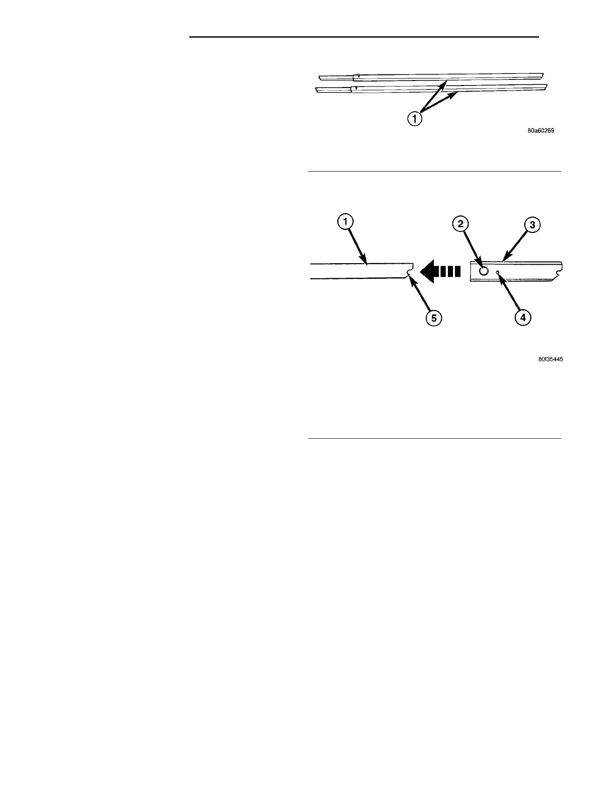
(6) Place Adapter, Special Tool 8897, over smaller
end of one of two Suspension Height Gages, Special
Tool 6914 (Fig. 7) (Fig. 8), aligning adapter locating
pin with notch in gage end.
(7) Tighten adapter thumb screw.
NOTE: The height gage with the adapter attached to
it is now the height gage to be used on the front
suspension.
NOTE: In order to achieve an accurate vehicle
height measurement, it is absolutely necessary to
position the height gages on the inner rim flange at
the very bottom of the wheel. That way the top sur-
face of each gage is parallel front-to-rear with bot-
tom surface of the frame rails.
Fig. 7 Special Tool 6914
1 - SPECIAL TOOL 6914
Fig. 8 Installing Tool 8997 On End Of Tool 6914
1 - HEIGHT GAGE 6914
2 - THUMB SCREW
3 - ADAPTER 8997
4 - LOCATING PIN
5 - NOTCH
2 - 62 WHEEL ALIGNMENT ZB
WHEEL ALIGNMENT (Continued)
 Loading...


