INCLINOMETER SETUP FOR CASTER ANGLE VIEWING
Both front and rear caster angle on this vehicle
can be read. Rather than using the alignment equip-
ment’s traditional sweep method, caster angles are
read directly off the front and rear knuckles through
inclinometer sensors, bracket mounted to the knuck-
les. These inclinometers are wired to the DRBIIIt
scan tool. Use Inclinometers, Special Tools 6989 (Fig.
15), Switch Box, Special Tool 6996 (Fig. 15), Front
Caster Adapters, Special Tool 8995, and Rear Caster
Adapters, Special Tools 8996, attached to a DRBIII
equipped with a PEP module capable of reading incli-
nometers.
NOTE: It is necessary to have a DRBIII with an
attached PEP module capable of reading inclinome-
ters.
(1) Plug cable from Switch Box, Special Tool 6996,
into PEP module connector on DRBIII marked
“INCL” (Fig. 16).
(2) Plug power cable (supplied with the DRBIII
kit) into DRBIII power connector marked “VEHI-
CLE” (Fig. 16).
(3) Attach two Inclinometers, Special Tool 6989, to
Switch Box (Fig. 15). Only two inclinometers are
supplied and should be used as a pair to mea-
sure either rear caster or front caster, one at a
time.
(4) Attach power cable from DRBIII to vehicle data
connector.
(5) At Main Menu screen, select “PEP Module
Tools.”
(6) At PEP Module Tools screen, select “Inclinome-
ter/Viper Alignment.”
NOTE: The inclinometer, Special Tool 6989, must be
zeroed (calibrated) prior to each time it is used to
read caster angle on vehicle.
(7) At Inclinometer Alignment screen, select “Read/
Display Angle.”
(8) Once at Read/Display Angle screen, if only one
inclinometer readout is shown, press F3 to show both
inclinometers.
Fig. 15 Inclinometers Installed On DRBIII
T
1 - SWITCHBOX 6996
2 - INCLINOMETERS 6989
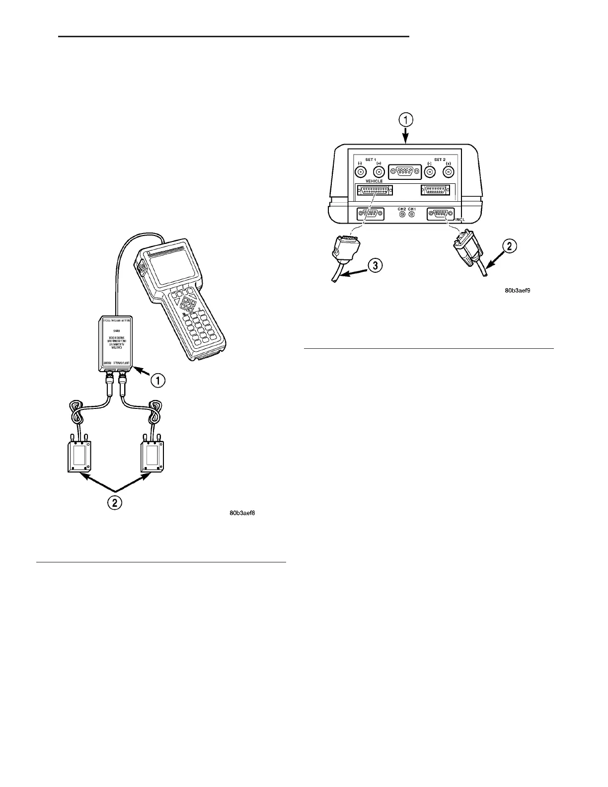
Fig. 16 Cable Connections At DRBIII
1 - DRB III
2 - FROM SWITCH BOX
3 - FROM VEHICLE POWER CONNECTION
ZB WHEEL ALIGNMENT 2 - 67
WHEEL ALIGNMENT (Continued)
 Loading...


