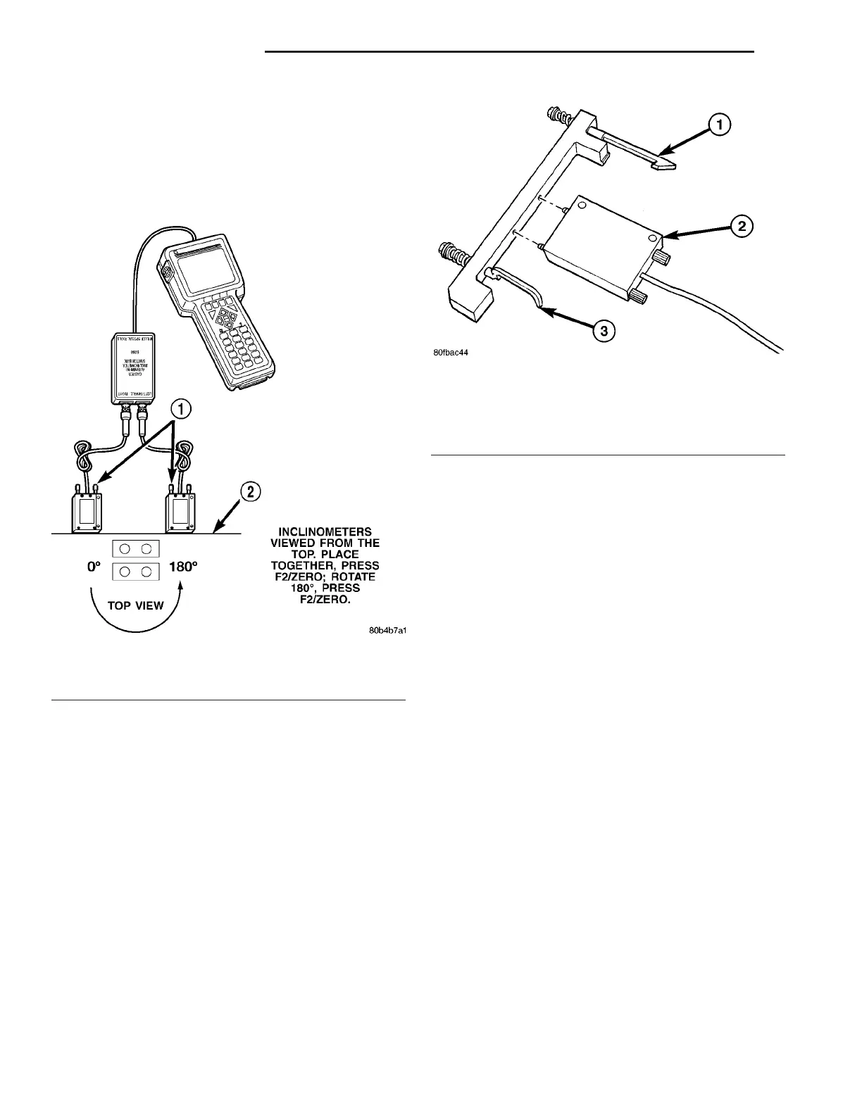
(9) Zero inclinometers (Fig. 17):
(a) Place both inclinometers together on known
flat, level surface, such as alignment rack, with
knurled ends of fastening screws facing upward.
(b) Press F2.
(c) Follow directions on DRBIIIt screen to com-
plete inclinometer zero.
(10) Since DRBIII can read only two inclinometer
measurements at a time, install inclinometers on
either front or rear knuckles and make necessary
adjustments, before transferring them to remaining
knuckles to measure caster.
INCLINOMETER INSTALLATION ON FRONT KNUCKLES
(1) Mount inclinometers to both front Caster Angle
Adapters, Special Tool 8995 (Fig. 18). Make sure
inclinometer from left side of Switch Box is mounted
to left adapter and inclinometer from right side of
Switch Box is mounted to right adapter. Adapters are
marked Left and Right. To make sure each inclinom-
eter is mounted right-side-up on Adapter, upper
mounting screw is larger diameter than lower.
(2) Clean any dirt or debris off knuckles paying
special attention to caster pads on leading end of
knuckles near ball joints.
CAUTION: Be sure caster pads on knuckles are
thoroughly cleaned before mounting Caster Adapt-
ers to knuckles. Caster Adapters must sit flat on
caster pads to obtain accurate caster readings.
(3) Insert each Adapter (with inclinometer
attached) through opening between upper control
arm and tie rod. Position Adapter lower spring-
loaded hook around lower ball joint nut and upper
spring-loaded hook over top of knuckle, then stretch
bracket forward, placing Adapter flats against caster
pads cast into leading side of knuckle (Fig. 19). Make
sure step built into Adapter upper flat is placed
against outside of upper caster pad as shown (Fig.
19) and not on face of caster pad.
(4) Adjust caster using measurements viewed on
DRBIII screen, and camber using measurements
viewed on wheel alignment equipment. (Refer to 2 -
SUSPENSION/WHEEL ALIGNMENT - SPECIFICA-
TIONS)
(5) When adjustments are complete, remove
Adapters/Inclinometers.
Fig. 17 Zero The Inclinometers
1 - KNURLED SCREWS
2 - FLAT AND LEVEL SURFACE
Fig. 18 Right Front Caster Adapter With
Inclinometer (Left Side Typical)
1 - UPPER SPRING-LOADED HOOK
2 - INCLINOMETER 6989
3 - LOWER SPRING-LOADED HOOK
2 - 68 WHEEL ALIGNMENT ZB
WHEEL ALIGNMENT (Continued)
 Loading...


