# Description # Description
B RS232 I Print Head 1
C Encoder 2 J I/O Terminal Block 1
D Print Head 2 K Print Head 3
E Print Head 4 L I/O Terminal Block 2
F Ethernet M Power Supply Input
G USB
-
Electrical connections are prepared outside of the controller. Cables are passed through a
protective cover into the controller and are sealed. This allows the controller's IP rating to be
maintained.
To maintain the IP rating, use the solid grommets to block holes in the seal that are not needed.
For easy access to the controller's USB sockets, it is recommended to connect a USB extension
cable to the controller through the protective cover and seal.
Required tools: 2.5 mm and 4 mm hex keys.
To make electrical connections to the Gx-IC10 Controller:
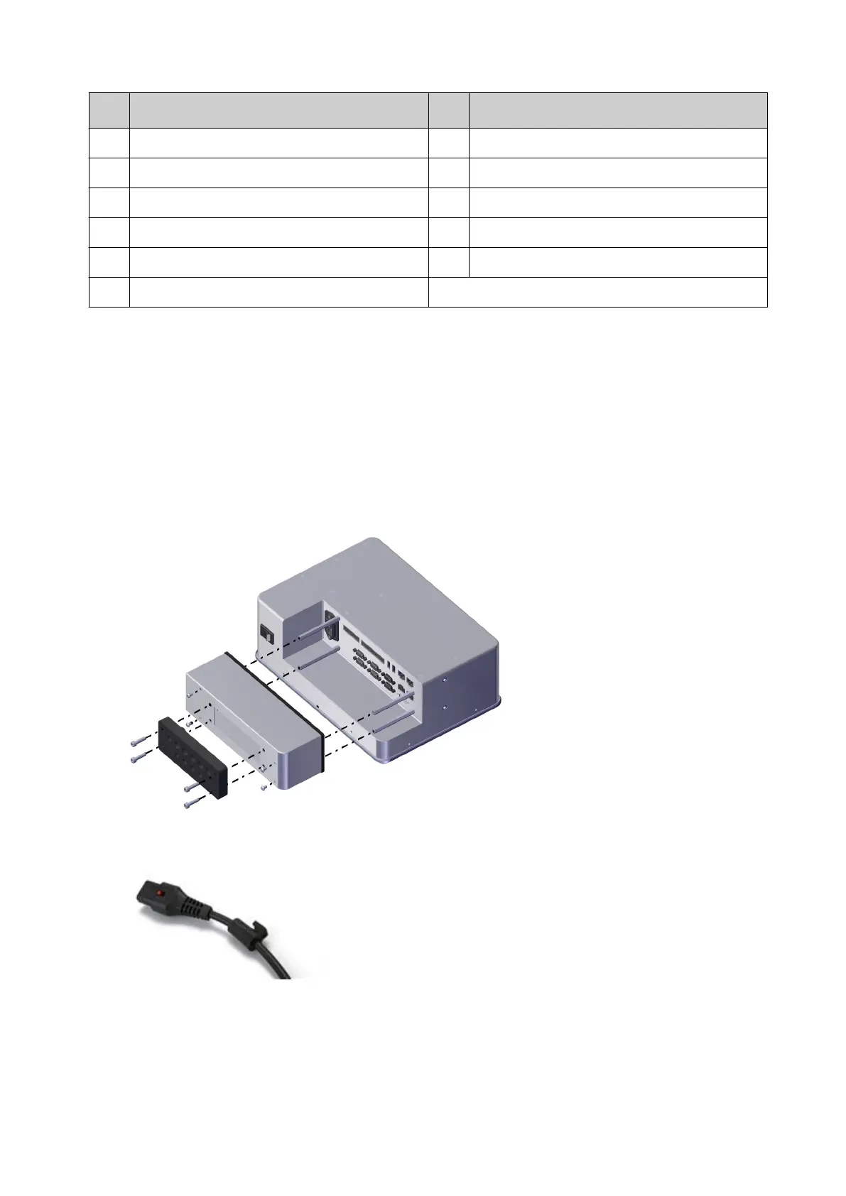
1. Remove the protective cover and seal.
Gx-IC10 Cover and Seal
2.
Put a grommet from the seal on each of the cables.
INSTALLATION
EPT053091 - Issue 5 - 07 May 2021 32
 Loading...