11
ED100LE 02-2021DL4616-001
dormakaba ED100 low energy operator – Fine cover
Installation Instructions
Chapter 4
. EDLE terminal board interfaces
TIPS AND RECOMMENDATIONS
• Use documentation provided
with each device for electrical
installation.
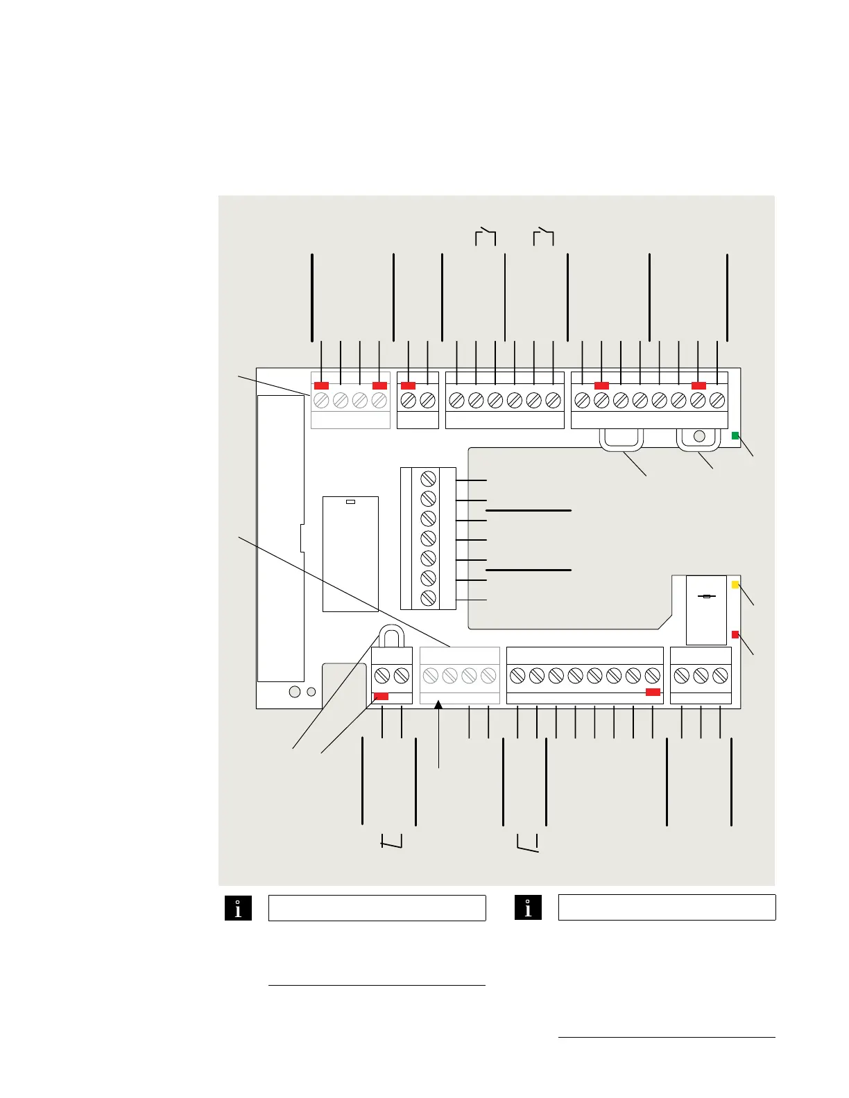
Fig. 4.1.1 Terminal board electrical connections
1 Green LED
2 Yellow LED
3 Red LED
4 Key (red insert)
location in socket.
Assigned plug has
tab in same location
broken off.
5 Jumpers, factory
installed at following
terminals:
• and a
• and *
• and *
6 DCW upgrade card
plug Not used.
7 Fire protection
upgrade card plug.
Not used.
TIPS AND RECOMMENDATIONS
• Do not connect system
accessories to board until
operator has been
commissioned and learning
cycle performed (Setup and
Troubleshooting Manual).
ELE terminal board interfaces
97 98 99 30 31 32 34 33 3335
1
36
1
4
4a
3
BA
1
57 57a
142
3
141
3
1
15
17
3
111
13 3
43 3646362
1G
3
+ 24 V
Signal input
0 V
Partial Open
Permanent Open
Exit Only
Automatic
Off
N.C.
COM
Test output
X5X4
X3
X6 X9 X1 X7
+ 24 V
X8
0 V
X10
8 - 24 AC/DC
+ 5% Wet
DCW bus
Activation inputs
Interior Exterior
Night-
bank
input
+ 24 V
Signal input
0 V
+ 24 V
+ 24 V
Signal input
Signal input
0 V
0 V
Test output
0 V
24 V
Maximum current
load: 1.5A
Output
COM
N.O.
N.C.
0 V
Locking relay
Maximum current:
1A, 48 V DC/AC
Locking feedback contact
Reference Note 1
0 V
0 V
+ 24 V
0 V
0 V
Signal input
N.O.
Smoke
detectors
Emergency
close
Night
trigger
Program, exit only
switches
Door status
24 VDC
Class II
1
2
3
4
5
6
7
5
5
Safety sensors
Swing side Approach side