26
ED100LE 02-2021DL4616-001
dormakaba ED100LE operator – Fine cover
Installation Instructions
Chapter 8
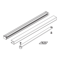
Fig. 8.8.1 ED100LE operator installation
1 Mounting plate
2 ED100 operator
3 Guide pin
4 115 Vac plug
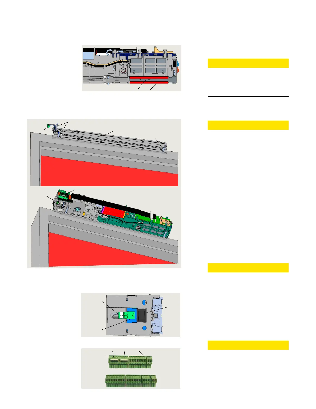
Fig. 8.8.2 115Vac plug and socket
4 115 Vac plug
6 115 Vac socket
7 Power off/on switch
Fig. 8.8.3 Terminal connectors
.. Install operator onto mounting plate.
CAUTION
Protective film strip removal.
Insure two protective film strips
have been removed from operator
heat conductive pads.
. Slide EDLE operator over the three
mounting plate guide pins and onto
mounting plate.
• Guide Vac plug () into housing
adjacent to socket ().
. Thread the eight captive M SHCS into
their mounting plate holes using
mm hex T-handle.
. Tighten the eight M SHCS.
.. Insert Vac plug into socket.
. Insert Vac plug from mounting plate
Vac terminal block into socket
(Fig. ..).
.. Full width cover option.
CAUTION
Program switch wiring.
Reference Appendix A for program
switch wiring terminal connections.
.. Connect accessory wiring.
. Use applicable terminal connectors
(Fig. ..) to terminate accessory
wiring.
. Use diagram in Chapter to locate
connector to its socket.
CAUTION
Safety sensor jumpers.
Jumpers (Fig. ..) must be in
place on safety sensor connectors.
• Reference Chapter .
5 Accessory wiring
terminal connectors
. Install EDLE operator onto mounting plate
11 Connectors
12 Jumpers
. Remove protective film strips from EDLE operator
1 Heat conductive pad
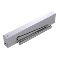
Fig. 8.7.1 Operator heat conductive pads
.. Remove protective film strips.
. Remove two protective film strips from
operator heat conductive pads.
CAUTION
Heat conductive pads.
Heat conductive pads must
remain clean once protective film
strips are removed!
1
4
6
7
1
4
3
2
5