44
ED100LE 02-2021DL4616-001
dormakaba ED100LE operator – Fine cover
Installation Instructions
Chapter 17
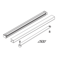
Fig. 17.1.2 Push arm backplate mounting
. Mount backplate, push arm application
Companion door, push arm installation
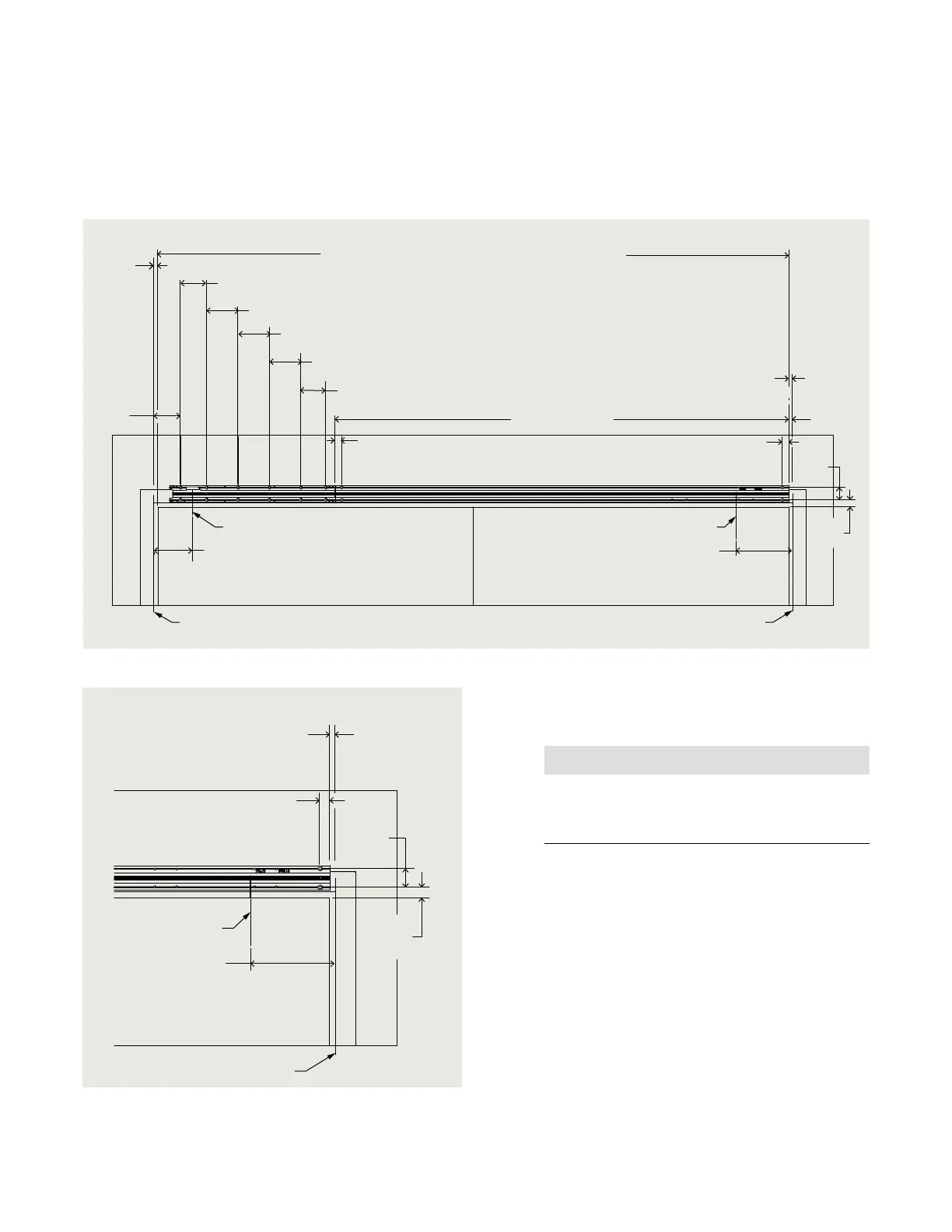
Fig. 17.1.1 ED100LE Companion backplate template; LH push version
Axle centerline
5 3/4”
[146.3]
8 9/16”
[216.7]
Axle centerline
Hinge pin centerline
Hinge pin centerline
ED100LE COMPANION PUSH
9/16”
[13.5]
To edge
of cover
FIXED
4”
[101.82]
3 15/16”
[100]
Cover length = centerline of hinge pin - 1 1/8” [28.5]
Cover and axle end are fixed and cannot be extended
4 3/4”
[120]
4 3/4”
[120]
4 3/4”
[120]
3 3/4”
[95]
1”
[25.4]
Closer backplate
1”
[25.4]
1 7/8”
[48]
1 1/16”
[26.9]
9/16”
[13.5]
To edge
of cover
FIXED
.. Install backplate, push arm application.
. Using backplate template (Fig. .. and ..),
locate left hand and right hand backplate mounting
holes on door frame/wall.
NOTICE
Template documents a LH push installation.
Template must be mirrored for a RH push
installation.
. Place backplate on door frame/wall and align with
the mounting hole locations in step .
• Check hinge pin centerline to edge of backplate
distance.
. Check backplate for level; adjust if necessary.
. Mark backplate mounting hole locations.
. Remove backplate and drill holes based on fastener
selected for door frame/wall material.
• Reference Para. . for backplate mounting screw kit.
• Use appropriate wall anchors if required.
. Place backplate on door frame/wall and secure with
fasteners (Step ).
8 9/16”
[216.7]
Axle centerline
Hinge pin centerline
1”
[25.4]
1 7/8”
[48]
1 1/16”
[26.9]
9/16”
[13.5]
To edge
of cover
FIXED