27
ED100LE 02-2021DL4616-001
dormakaba ED100LE operator – Fine cover
Installation Instructions
Chapter 9
Push arm installation
NOTICE
Reference Chapter 7 – EDLE installation
templates.
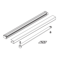
Fig. 9.1.1 Push arm assemblies
1 Standard push arm
2 Deep push arm
. Push arm installation
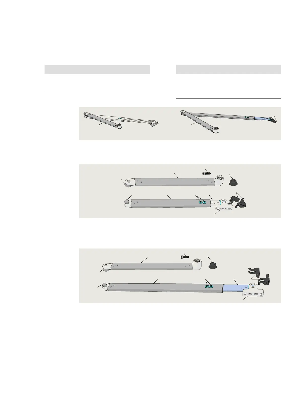
Fig. 9.2.1 Splined push arm assembly, 8 75" [225] DC4677-01X
1 Splined drive arm
2 Socket
4 Adjustment arm
11 1/4"[285]
5 Adjustment arm
tube 12 1/4" [311]
6 Shoe
7 M6 x 10 mm flanged
button head screw
8 Ball head
11 Shoe screw cover
12 M8 x ___ SHCS
13 Cap
Fig. 9.2.2 Splined push arm assembly, 19 11/16" [500] DC4677-02X
1 Splined drive arm
2 Socket
6 Shoe
7 M6 x 10 mm flanged
button head screw
8 Ball head
9 Adjustment arm,
17 3/4" [450]
10 Adjustment arm
tube, 17 3/4" [450]
11 Shoe screw cover
12 M8 x ___ SHCS
13 Cap
. Push arm installation templates
2
1
4
5
7
6
8
11
1
12
2
13
1
2
8
10
9
7
6
11
12
13
NOTICE
Double door push arm installation.
Repeat steps in Chapter 9 for each push arm
installation.