47
ED100LE 02-2021DL4616-001
dormakaba ED100LE operator – Fine cover
Installation Instructions
Chapter 17
.. Drill two holes in door for
adjustment arm shoe fasteners.
Push arm installation template (Chapter )
documents location of shoe on door.
. Drill holes in door for adjustment arm
shoe fasteners. Reference push arm
screw kit (Fig. ..).
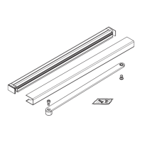
.. Install adjustment arm assembly
on door.
. Fasten adjustment arm assembly to door.
. Insure arm is at installation height as
shown on push arm installation template.
NOTICE
Check shoe for level.
Check adjustment arm shoe for
level as fasteners are tightened.
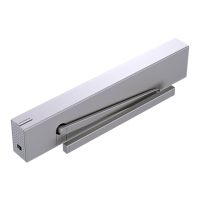
.. Connect adjustment arm to drive
arm.
. Loosen the two adjustment M x mm
flanged button head screws..
. Using square, position adjustment arm
assembly at angle to door.
. Adjust length of adjustment arm until
drive arm ball head is aligned with
adjustment arm socket.
CAUTION
Maintain adjustment arm
assembly at a angle to door.
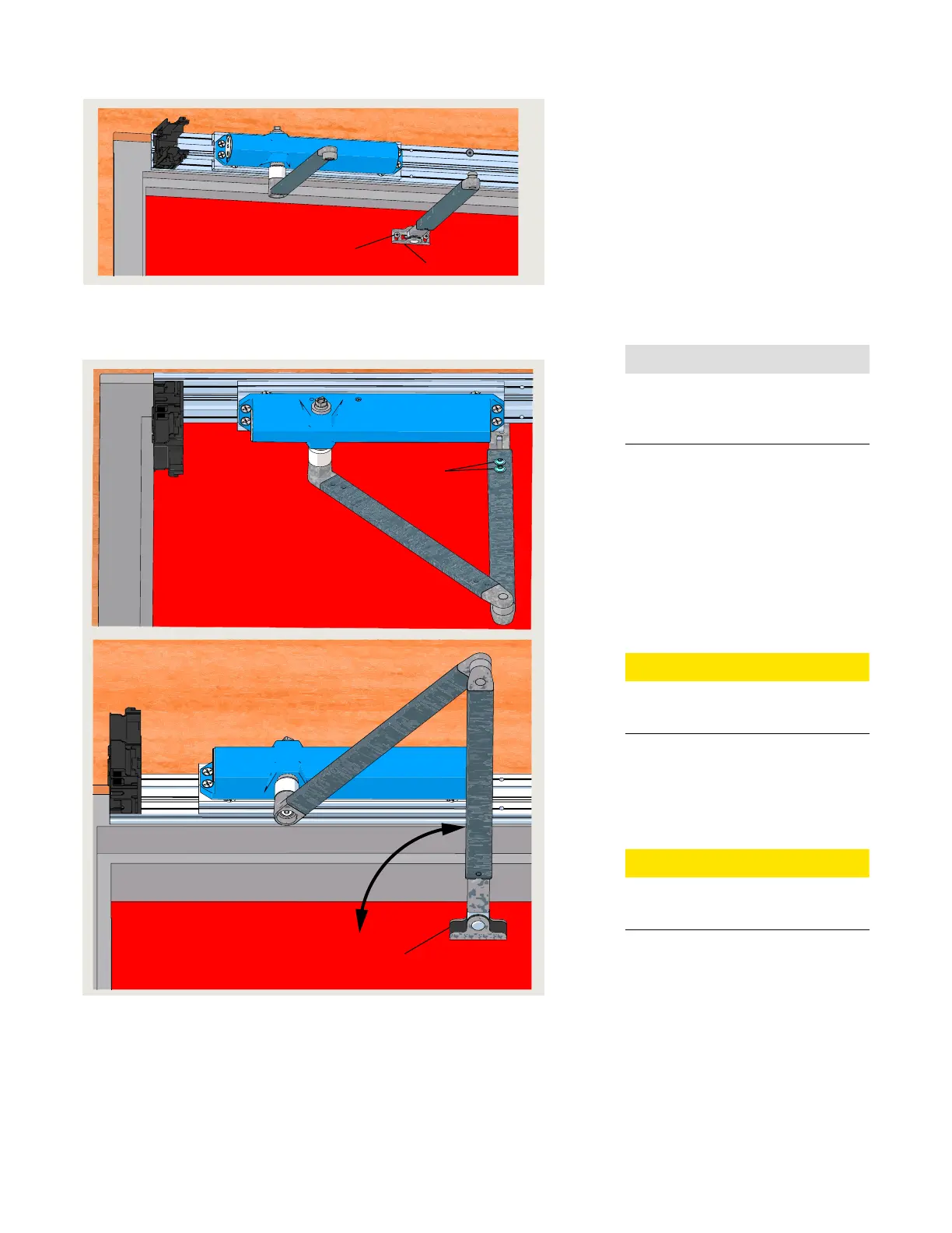
. Insert adjustment arm ball head into
drive arm socket.
. Secure adjustment arm position by
tightening the two M x mm flanged
button head screws.
CAUTION
Recheck that adjustment arm is
at angle to door.
.. Install shoe screw covers.
. Install shoe screw covers.
.. Door closer adjustments.
Reference Chapter .
4
90°
(2) 5
Fig. 17.3.6 Connecting drive arm to adjustment arm
4 M6 x 10 mm flanged
button head screw
5 Shoe screw cover
Fig. 17.3.5 Adjustment arm installation
(2) 2
1
2 10-24 x 1 " pan
head Philips screw
1 Adjustment arm
shoe