58
ED100LE 02-2021DL4616-001
dormakaba ED100 low energy operator – Fine cover
Installation Instructions
Appendix A
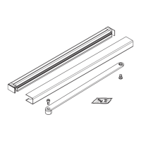
Fig. A.2.4 Mounting plate connectors and fasteners
4 Mounting plate
extr connector
HC3491-010
5 ED100LE operator
mounting plate
4
4
8
8
9
9
6
5
5
6 Backplate, ED
operator FC Ext
HC3468-010
8 M6 x 10 mm SHS
with washer
DF3495-01Z
9 M6 x 10 mm PFHS
DF3496-01Z
4
. Secure the operator mounting plates to the pair
mounting plate () using:
• () mounting plate connectors ()
• () M x mm SHS with washer (8)
• () M x mm PFHS ()
Do not tighten screws.
A.. Check cover fit over ED operators.
. Place the ED operators onto their mounting plates
(Para. )
. Place end caps () at end of each operator.
. Place cover over end caps and EDLE operator.
. Adjust mounting plates as necessary for cover fit
over end caps.
. Remove end caps and operators.
. Tighten mounting plate connector fasteners.
A.. Mounting plate installation.
. Reference Para. ..
A.. Install program switch.
. Once header is installed, single program switch must
be installed in fine cover end cap opposite the power
switch.
. Program switch wires to the active door operator
(Fig. A..).
A.. Install Service Call label in cover.
. Install Service Call label (Fig. A..) on inside of cover.
• Service call label included in Low Energy label kit
HK3137-030.
Fig. A.2.6 ED100LE program switch wiring
13
Fig. A.2.5 Program switch and cable
13 Program switch
HX3486-030
30
31
32 33
34
3
35
3
Brown
Green
White
X1
13
Yellow
13 Program switch
HX3486-030
1 Label, Service call,
DD3425-010
1
Fig. A.2.7 Label, service call