42
Accessories
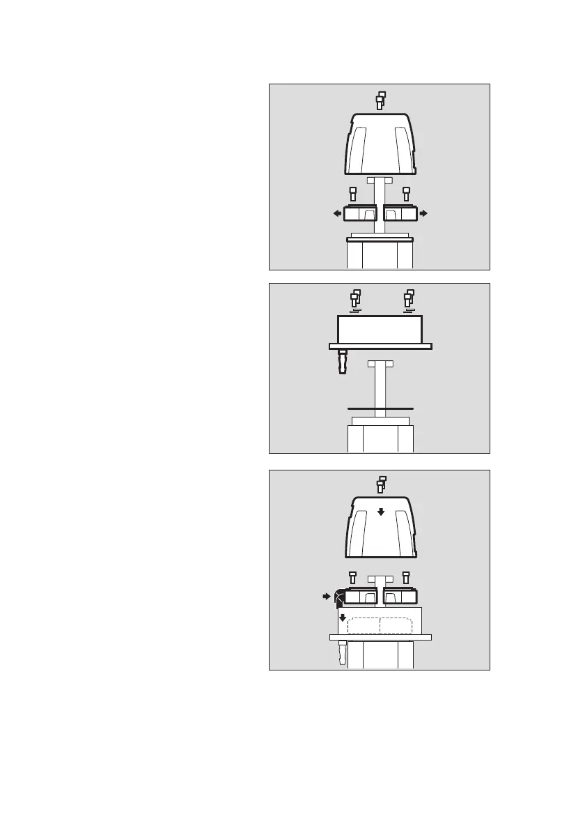
Prepare the gas transmitter for installation:
1 Dismount the splash guard PIR 7000 /
7200 (if available).
2 Remove status indicator PIR 7000 /
7200, flowcell PIR 7000 / 7200, bump
test adapter PIR 7000 / 7200 (if
available).
3 Remove the joint ring PIR 7000 (if
available).
Assemble the duct mount set:
● Clean sealing surfaces of gas transmitter,
if necessary. It is important to let the
sealing surfaces and the bottom of the
measuring cuvette dry completely .
● Position the flat gasket (1) and the ring
with screwed-in nozzles (2) onto the gas
transmitter and secure it by evenly tighten
four screws M5 x 12 with washers.
● If the nozzles (gas inlet and gas outlet) are
not needed, close them gastight, e.g. by
connecting them with a short piece of
hose and moisten slightly, if necessary.
Assembly of flowcell resp. bump test
adapter:
4 Flowcell PIR 7000 duct (part no.
68 11 945, see page 44) and/or bump
test adapter PIR 7000 duct (part no.
68 11 990, see page 44).
5 Moisten the inside of the two angled
elastomer connectors and slide the
connectors onto the flowcell resp. the
bump test adapter up to the stop.
6 Fix the flowcell and/or bump test adapter
into the ring. Slide the angled connectors
onto the nozzles in the ring.
● Then fix the flowcell resp. the bump test
adapter by tightening the 2 screws.
7 If required: Mount the splash guard onto
the gas transmitter with the two screws.
05023886_01.eps
1
22
3
05123886_01.eps
2
1
05223886_01.eps
7
45
6

 Loading...


