44
Accessories
Flowcell PIR 7000 Duct
*)
(Part no. 68 11 945)
— In combination with the duct mount set PIR 7000, the PIR 7000 Duct flowcell is intended
for testing the function of the gas transmitter with high test gas concentration and external
test gas feed.
— Dräger Safety recommends a test gas flow of 0.5 to 1.0 L/min. The gas flow should be
monitored.
— For gas transmitters with or without splash guard.
— The performance characteristics of the gas transmitter are influenced by flowcell. A
calibration of zero-point and sensitivity (span) is therefore necessary after assembly or
disassembly of the flowcell!
— For further information, see page 32.
Bump Test Adapter PIR 7000 Duct
*)
(Part no. 68 11 990)
— In combination with the duct mount set PIR 7000, the bump test adapter PIR 7000 Duct is
intended for testing the function of the gas transmitter (with splash guard) with a gas/air
mix in concentrations below the lower explosion limit (test gas).
— Since dilution effects (convection current, wind) may lead to concentrations lower than that
of the test gas in the measuring cuvette of the gas transmitter, the bump test adapter is not
generally suitable for calibration purposes.
Notices on operation:
● In order to minimise the effect of flow during function test, gassing of the gas transmitter
via the bump test adapter should be done with no less than 10 litre of test gas per minute.
Suitable pressure reducers should be used for this purpose.
● Operation with a bump test adapter does not influence the performance characteristics
and the approvals of the gas transmitter.
● For further information, see page 35.
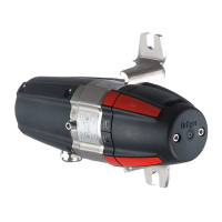
The gas transmitter features two status lights and provides the following information:
— Continuous green for indicating operational readiness
— Continuous yellow for displaying a fault
— Flashing green/yellow for status messages during the calibration procedure.
These light signals are arranged on two opposing sides of the flowcell or the bump test
adapter.
*)
The flowcell PIR 7000 duct as well as the bump test adapter PIR 7000 duct are also suitable for the use with Dräger PIR 7200.
NOTICE
The allocation of light signals relative to the upper / lower side of the gas transmitter may be
reversed depending on the assembly of the gas transmitter. Basically the colour allocation
(yellow/green) does not determine the position of the light signals on the status indicator.
Dräger Safety recommends proper attachment of the labels (Power/Fault) at the outlets of
the light signals.
 Loading...
