EasyManuals Logo

Dräger Polytron 8000 Series Technical Manual

Dräger Polytron 8000 Series
110 pages
To Next Page IconTo Next Page
To Previous Page IconTo Previous Page
Page #24 background imageLoading...
Page #24 background image
24 Technical Manual | Dräger Polytron
®
8000 Series
Installation
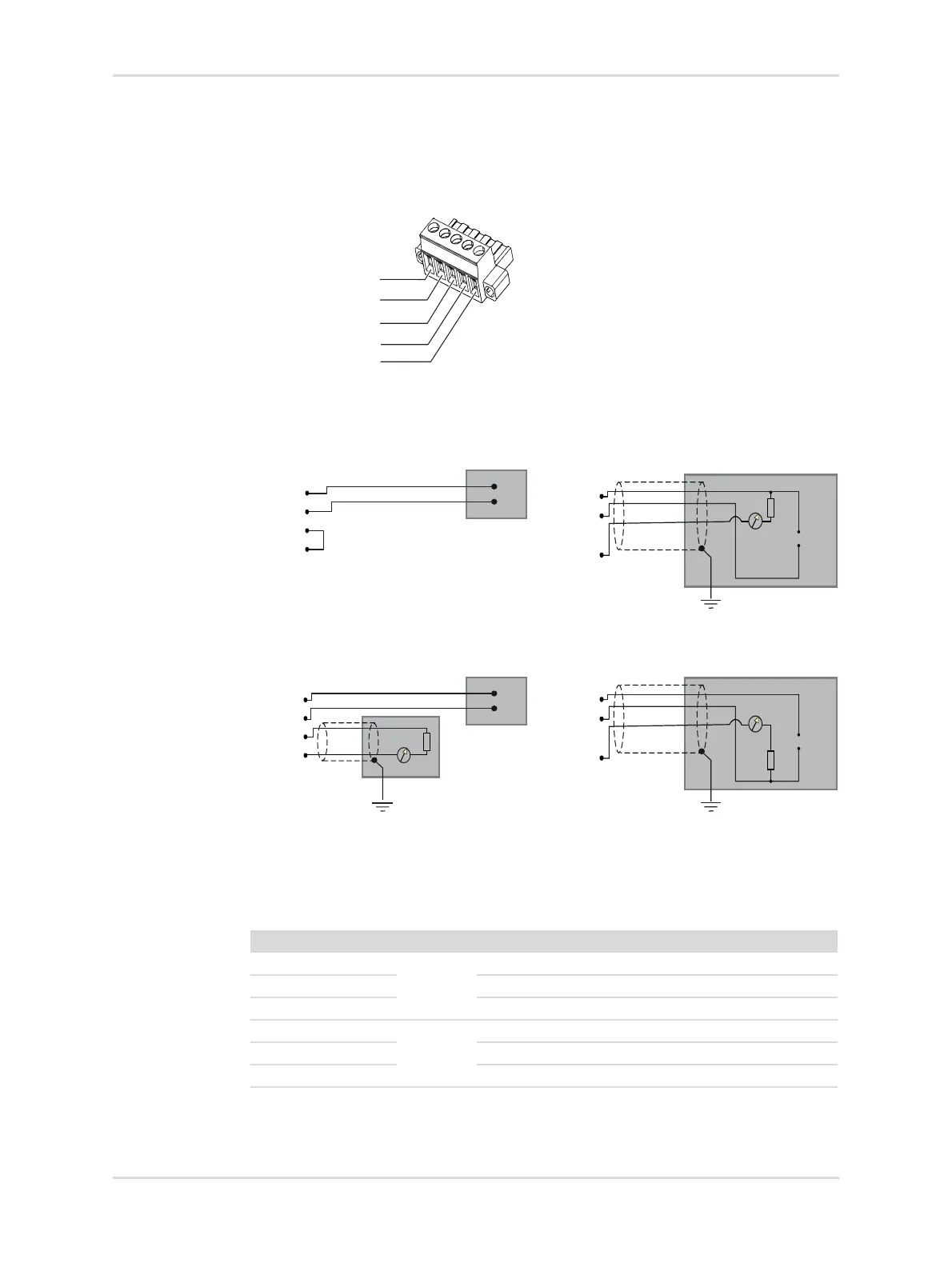
5-pin connector for 4-20 mA and HART
®
connections
Galvanic separation of a separate power supply and analog signal output is not
possible (pin 2 and 3 are connected within the 5-pin connector).
Wiring figures
Relay connector
The relay labels (NO, COM, NC) represent the default state (normally energized) of
all relays while the instrument is powered.
44798
Stand-alone, relay only
4-20 mA / HART
®
(Current sink)
4-20 mA / HART
®
(Separate power) 4-20 mA / HART
®
(Current source)
Pin Mark Relay
1 NO FLT Fault Normally Open
2 COM Fault Common
3 NC Fault Normally Closed
4 NO A2 A2 Normally Open
5COM A2 Common
6 NC A2 Normally Closed
3 - PWR-
2 - PWR-
1 - PWR+
4 - 4-20mA
5 - PE
PWR+
PWR-
PWR-
4-20 mA
PE
VDC
+
-
VDC
+
-
mA
PWR+
PWR-
PWR-
4-20 mA
PE
mA
PWR+
PWR-
PWR-
4-20 mA
PE
VDC
+
-
VDC
+
-
mA
PWR+
PWR-
PWR-
4-20 mA
PE

Table of Contents

Other manuals for Dräger Polytron 8000 Series

Questions and Answers:

Question and Answer IconNeed help?

Do you have a question about the Dräger Polytron 8000 Series and is the answer not in the manual?

Dräger Polytron 8000 Series Specifications

General IconGeneral
Ingress ProtectionIP66/67
Detection PrincipleElectrochemical, Infrared, Catalytic Bead
Gases DetectedCombustible gases, toxic gases, and oxygen
DisplayLCD with backlight
Humidity Range0 to 99% RH (non-condensing)
Housing MaterialStainless steel
Output Signal4-20 mA, HART, RS-485 Modbus
Power Supply10 to 30 V DC
CertificationsATEX, IECEx, CSA
Temperature Range-40 °C to +65 °C (depending on sensor)

Related product manuals