28 Technical Manual | Dräger Polytron
®
8000 Series
Installation
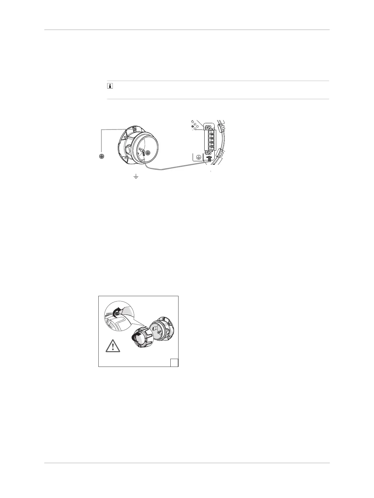
1. Ground the enclosure of the instrument locally at the grounding lug, see the
following figure.
2. Connect the shield of the wires only to the instrument earth ground of the
controller (e g. chassis, ground busbar, etc.).
Unless special measures are taken (e. g. capacitive earthing), the shield must
only be connected at one end.
Fig. 3 Grounding the Ex d enclosure and the PCB unit
5.2.9 Closing the instrument
1. Ensure the following connections are properly made:
a. Wiring screws are tightened to the correct torque.
b. All cable connectors are secured with screws.
c. The sensor connector is plugged.
d. The grounding cable coming from the enclosure is connected to the lug on
the PCB unit, Grounding the Ex d enclosure and the PCB unit
2. Place PCB unit back into the enclosure.
3. Screw the lid back on, until it is seated with correct torque, and tighten set-
screw.
Fig. 4 Closing the Ex d enclosure with correct torques
5.3 Installing EC sensor
Observe the following figure.
This point is only valid for Polytron
®
8100 EC
1. If the instrument is already in operation, activate the function to change the
sensor (Sensor change function). Otherwise, a fault is displayed when the
sensor is deplugged.
38743
Without relay:
Polytron 8xx0
PWR+
PWR-
PWR-
4-20 mA
PE
40515
≥ 44 LB IN
≥ 5 Nm
≥ 8 LB IN
≥ 0.7 Nm
E

 Loading...


