Technical Manual | Dräger Polytron
®
8000 Series 71
Interface settings
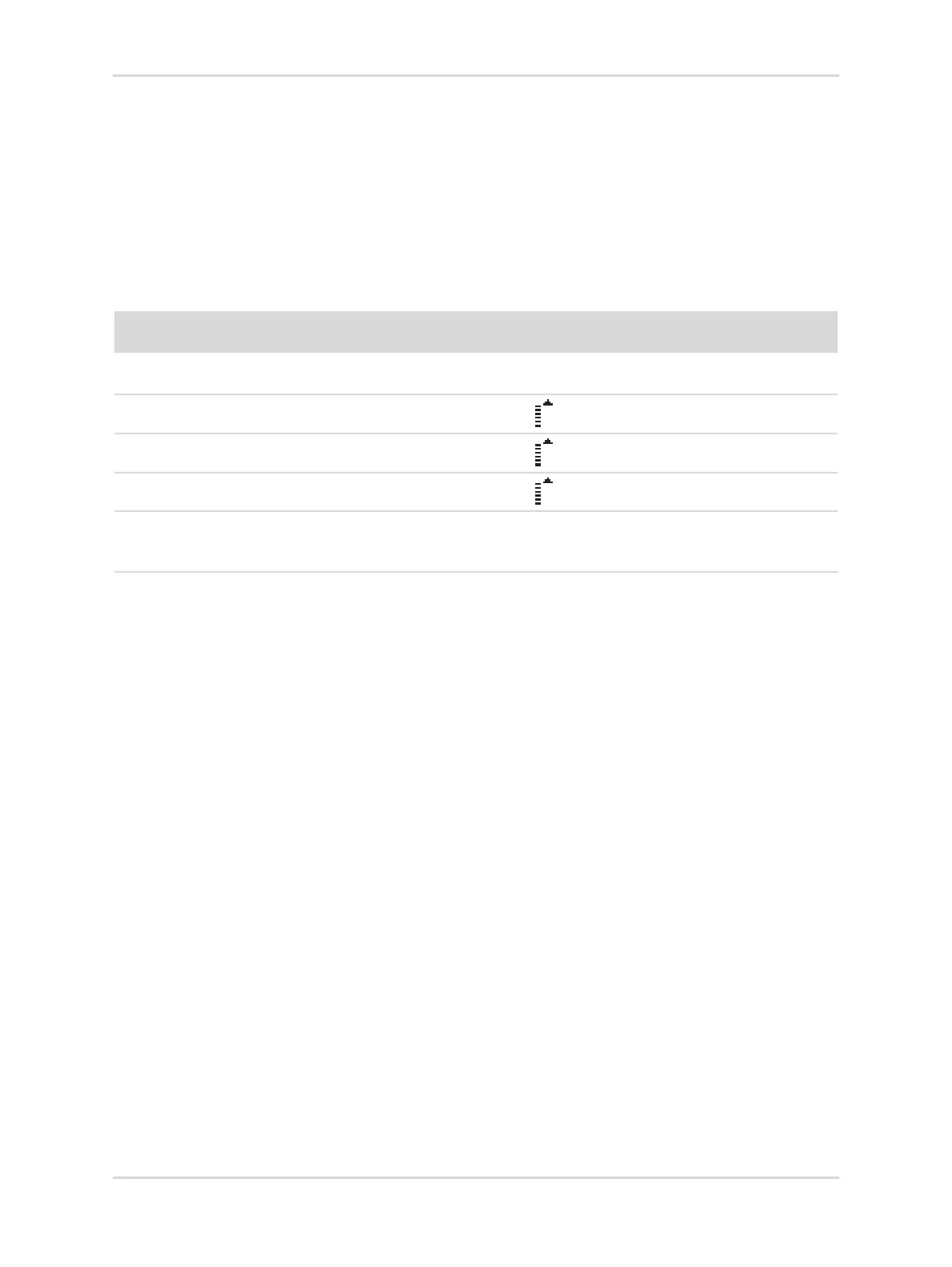
The following table shows the correlation between Display indication, relays and
analog interface output depending on assumed values.
Assumed values:
LC sensor (measuring range: 5-10% LEL),
A1 = 8% LEL,
A2 = 9% LEL,
FSD = 7% LEL.
13.1.2 Setting fault current
This function defines the current for the fault signal.
1. Select Settings > Communication > Analog interface >Fault current and
confirm.
2. Select the line for editing the current and confirm.
3. Set the current and confirm.
The setting for the Fault current is displayed.
4. Select Confirm and confirm with [OK].
13.1.3 Information regarding the warning signal
To transmit a warning signal via the analog interface, the warning signal must be
switched on.
The warning signal alternates between the warning current and the measurement
current.
– Warning current (interval T2)
– Measurement current (interval T1-T2)
Gas Concentra-
tion
Relays Display Analog interface
6.5 % LEL no change Measured value Linear current between 4
and 20mA
7.5 % LEL no change
Measured value and
20mA
8.5 % LEL A1 switches
Measured value and
20mA
9.5 % LEL A1 and A2 switch
Measured value and
20mA
10.5 % LEL A1 and A2 switch 4 upwards-pointing arrows
Value is over measuring range of
the sensor.
20mA

 Loading...


