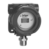
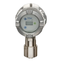
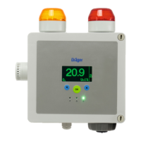
90 Technical Manual | Dräger Polytron
®
8000 Series
Technical data
Impedance of the signal loop
For further information regarding the fieldbus interface installation consult the
corresponding Technical Hanbook.
17.3 Cable specifications
For non-conduit installations, use shielded cables.
17.4 Power supply and relays
Operating mode Impedance range of
the signal loop
Supply voltage range
Operation without
HART
®
communi-
cation
0 to 230 at 10 V DC
Rising linearly with the
supply voltage from:
0 to 230 at 10 V to
0 to 500 at 16 V
10 to 18 V DC
0 to 500 18 to 30 V DC
Operation with
HART
®
communi-
cation
230 to 270 at 13 V DC
Rising linearly with the
supply voltage from:
230 to 270 at 11 V to
230 to 500 at 16 V
11 to 16 V DC
230 to 500 18 to 30 V DC
HART
®
Multidrop
operation
230 to 500 10 to 30 V DC
Analog and HART
®
connection with control unit and power supply
Power supply and signals 3-core shielded cable
24 - 12 AWG / 0.2 - 2.5 mm²
Relays 20 - 12 AWG / 0.5 - 2.5 mm²
Digital connection with control unit
Instruments with fieldbus interfaces and remote sensors must be installed with
shielded cables.
Modbus RTU 4-core, AWG 26
PROFIBUS
®
PA
Foundation
TM
Fieldbus
2-core, Cable type A
Wave impedance R
w:135 - 165
Capacitance / unit length C‘:< 30 pF/m
Loop resistance R‘:110 /km
Core diameter d:0.64 mm
Core cross section q:> 0.34 mm²
Shield coverage:> 90 %
Power supply 24 - 12 AWG / 0.2 - 2.5 mm²
Relay rating
1)
SPDT
2)
230 V
0.1 A - 5 A
 Loading...


