Do you have a question about the Dranetz Xplorer and is the answer not in the manual?
Ensure the instrument's internal battery is fully charged before initial use.
Configure the instrument's time zone and date settings for accurate logging.
Instructions for connecting the instrument to an AC power source safely.
Overview of the Home Screen and Home Monitoring Screen for instrument access.
Identifies controls and connectors on the top panel of the instrument.
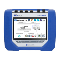
Details the color LCD, touch screen, power indicator, and touch icons.
Locates power switch, GPS receiver, and AC adapter connector on the left panel.
Identifies Ethernet and USB ports on the right panel for connectivity.
Describes the device mounting hanger, wire coil holders, and stand.
Information on measurement cable sets, jumpers, and optional adapters.
Wiring diagrams for 3 Phase Wye and Delta configurations.
Explains the interactive icon graphics at the top of the user interface.
Describes the display area and context-sensitive soft function keys.
Takes a snapshot of the current screen and saves it.
Opens or closes a mini report for saving data.
Provides instant on-screen help based on the active screen.
Displays monitoring status, file name, duration, and memory usage.
Explains how to use taskbar shortcuts and bottom screen icons.
Options to start, stop, or configure monitoring sessions.
Accesses instrument configuration settings like time and language.
Displays live voltage and current measurements in various modes.
Views captured data in graphic or textual form, including events.
Introduces Automatic Setup and Wizard Setup for monitoring configuration.
Automatically configures circuit type, parameters, and thresholds.
Step-by-step guidance for circuit setup and monitoring settings.
Explains various modes like Power Quality, Inrush, Fault Recorder, etc.
Review/modify limits for RMS variation and record amount.
Configuration for peak, waveshape, RMS diff, and high frequency transients.
Set trigger channels, parameters, and data save intervals.
Specific settings for EN50160 Voltage Compliance monitoring.
Setting up start/stop conditions, memory, and optional info.
Choices for saving, using as meter, or exiting setup.
Load previously saved setup configurations from memory or USB.
Access and manage recorded monitoring sessions and data files.
Modify settings like time, language, and communications options.
Save current monitoring settings to memory or USB.
Details miscellaneous tasks for efficient instrument operation.
Details Ethernet, WiFi, Bluetooth, VNC, and Modbus connections.
Procedures for downloading data remotely and via USB.
Oscilloscope-like display of real-time voltage and current waveforms.
Graphical dial-type display of selected parameters.
Tabular display of metered parameters organized by category.
Visual overview of parameter status, limits, and event counts.
Accesses various event data and report views.
Summary of captured events with date, time, and classification.
Displays events as RMS plots or graphical waveforms.
Detailed information for each captured event, including parameters.
Displays QOS evaluation status and compliance history.
Shows distribution of dips and min/max values for parameters.
Provides options to view demand and energy reports for consumption analysis.
Generates harmonic statistics based on IEC standards.
Details dimensions, weight, environmental, and installation categories.
Includes warranty, FCC compliance, proprietary rights, copyright, and trademarks.
| Category | Power Quality Analyzer |
|---|---|
| Type | Portable Power Quality Monitor |
| Model | Xplorer |
| Channels | 8 |
| Voltage Channels | 4 |
| Current Channels | 4 |
| Voltage Accuracy | ±0.1% of reading |
| Current Accuracy | Clamp dependent |
| Display | Color touchscreen LCD |
| Transient Capture | Yes |
| Communications | Ethernet, USB |
| Memory | Internal flash memory, expandable via SD card |
| Communication Interfaces | Ethernet, USB |
| Power Quality Measurements | Voltage, current, power, energy, harmonics, flicker, transients, sags, swells, interruptions |
| Standards Compliance | IEC 61000-4-30 Class A, IEEE 1159, EN 50160 |