10 | Channel setup menu 4
D-ISC 100 x xx2
101
Menu: 4.2.S1.2.0
Info: Filter Off
S1:Messages
\\Channel setup\Sensor (S)\S1\Messages
Startup (extern reset) [002]
Startup (power on) [001]
E
Startup (watchdog reset) [003]
Startup (bod reset) [004]
Startup (with default jumper) [005]
Zero point check running [006]
Menu: 4.2.S1.2.0
Info: Filter On
S1:Messages
\\Channel setup\Sensor (S)\S1\Messages
Device temperature too high [082]
Hardware fault [192]
E
Linearity check running [015]
!
x
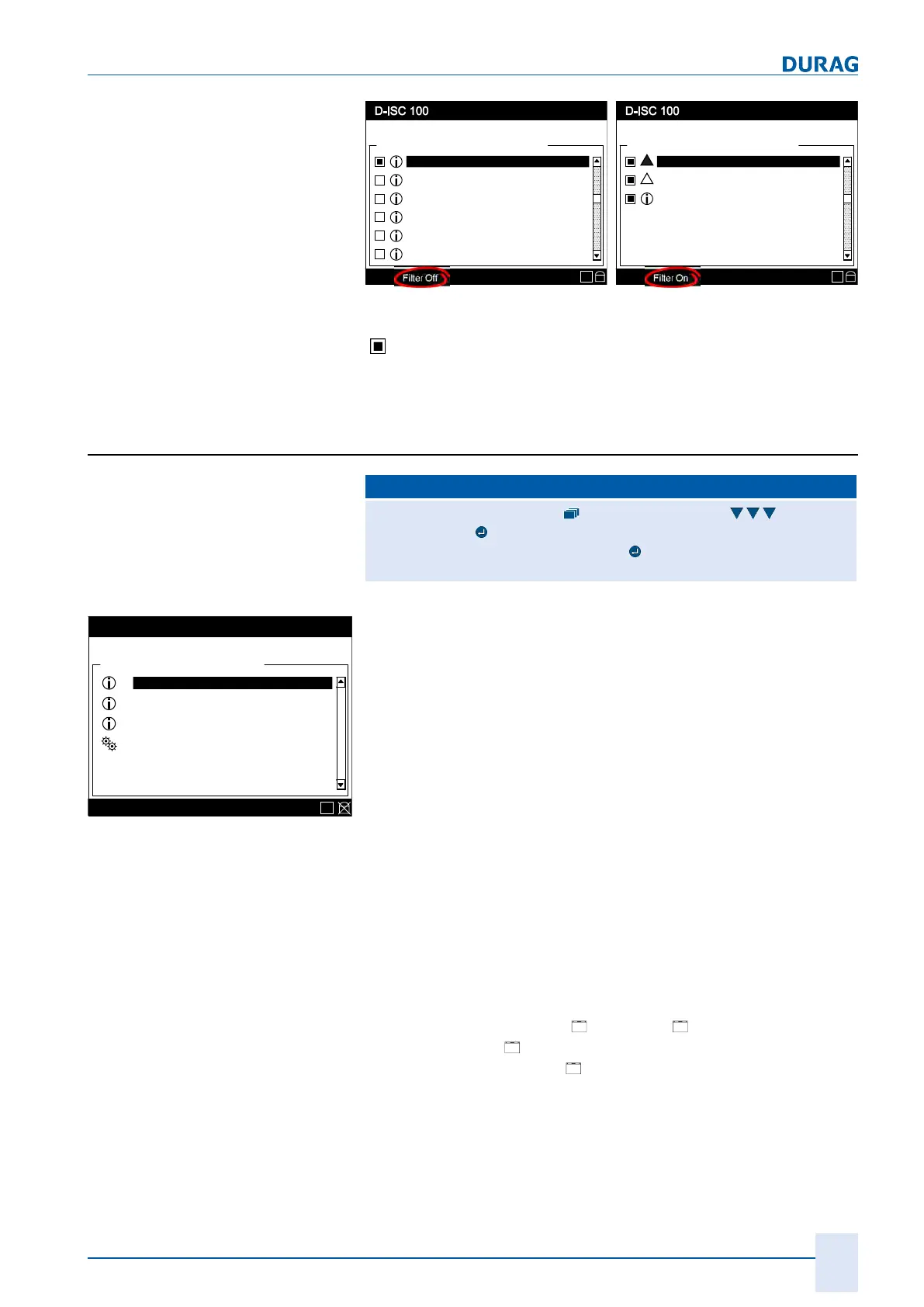
Fig.10.7: Example: all messages (unfiltered)/messages filtered
Only the currently pending messages will be shown as active
(
). Messages that are no longer pending can be viewed in the
device message log using the (optional) software DURAG Engin-
eering and Service Interface D‑ESI100.
10.2 Menü D-ISC 100 (D): Universal operation unit
D‑ISC100 menu path:
Standard display (e.g. S1.1) User mode (menu1) Channel
setup (menu4)
D−ISC100 (D) (menu4.1) D-ISC100
= Device status MENU 4.1.1
Menu: 4.1.1
Status: S1.3:Normal measurement
D-ISC 100 (D)
\\Menu\Channel setup\D-ISC 100 (D)
Device status
Specific parameter
Messages
Device status extended
Functions
E
Fig.10.8: Channel setup D-ISC 100 (D)
This menu item reports the status, messages and functions that
relate to the D-ISC 100 basic system and the overall system.
All faults (F) in the system are displayed centrally in this menu
item (see Combined fault [}101])and can then be processed in
a targeted manner.
Combined fault
A fault in the D‑ISC100 system and its connected units (sensors,
modules, channels, ...) is initially only flagged in the status of the
unit in which it occurs. This would mean that all the relevant
menus would have to be accessed to check the status in order to
determine the cause of the fault. The system triggers a combined
fault in order to reduce this effort.
A combined fault is issued at the higher levels, while one or more
faults are reported in one or more subordinate levels.
Status messages such as "
Fault (F), " Maintenance/Check
function (C)" and "
Maintenance demand (M)" are inherited by
the overall device status ("
Device status") from the connected
sensors and expansion modules and are flagged by the respect-
ive LED.
The statuses and messages for the individual system compon-
ents are then investigated for a more precise fault analysis.

 Loading...