3 | Device and Function description
D-ISC 100 x xx2
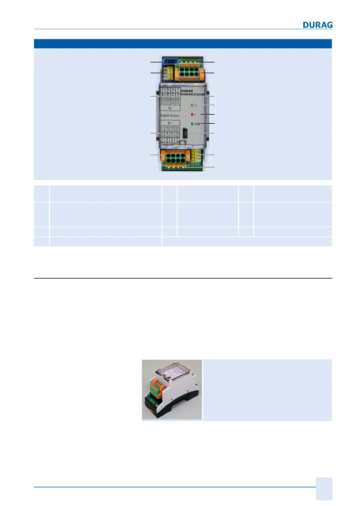
25
Top hat rail module
41a
42
43
41b
41c
41d
44
45
41a
47
45
46
46
42
41a
LED (orange): there is current at the re-
lay
coil
42
Module
connecting terminals
45
Changeover switch for
relay NO/NC
41b
Ready-for-operation LED (green);
flashes
during internal communication
43
Hinged cover
46
Terminal assignment of
module connecting termin-
als
41c
Fault LED (red) expansion module
44
USB port
47
Service
41d
USB connected LED (blue)
Some of the described components are type-specific, and are not present on all modules
Table3.14: Top hat rail module
3.4 Expansion modules
Top hat rail expansion modules and software expansion modules
are available for the D‑ISC100.
Top hat rail expansion modules
Top hat rail expansion modules are fitted onto the top hat rail in-
side the device.
The usability depends on the D-ISC100 version being used (see
3.2 Variants, design types [}16]).
Analogue output (AO)
Top hat rail expansion module
see also 4.3.4 Analogue output [}53]
One
analogue output is integrated into the universal operation
unit.
An optional analogue output expansion module D‑ISC100 (mod-
ule - analogue OUT) is available for 4 additional analogue out-
puts per device.
 Loading...