4 | Installation and commissioning
D-ISC 100 x xx2
45
In principle, a D‑ISC100 can only operate/parameterise those
sensors that are connected via the Modbus Master interface of a
D‑ISC100. The following therefore applies:
D‑ISC100 Operates/parameterises sensor
(Db) (Sa)
(Dc) (Sb)
(Da) (Sa) and (Sb)
All buses must be terminated at each end. This termination can
be switched on and off in the individual devices (see relevant
manual).
In this example, the D‑ISC100 (Da) serves as an interface
between the sensor system and the PLC [}204] .
The PLC can be connected via analogue and digital I/O [}203]s,
Modbus RTU [}204] or Modbus TCP [}204]. Optional expansion
modules may be required here.
Details regarding the connection of the data cable can be found
in Section 4.2.4 Bus connection [}36].
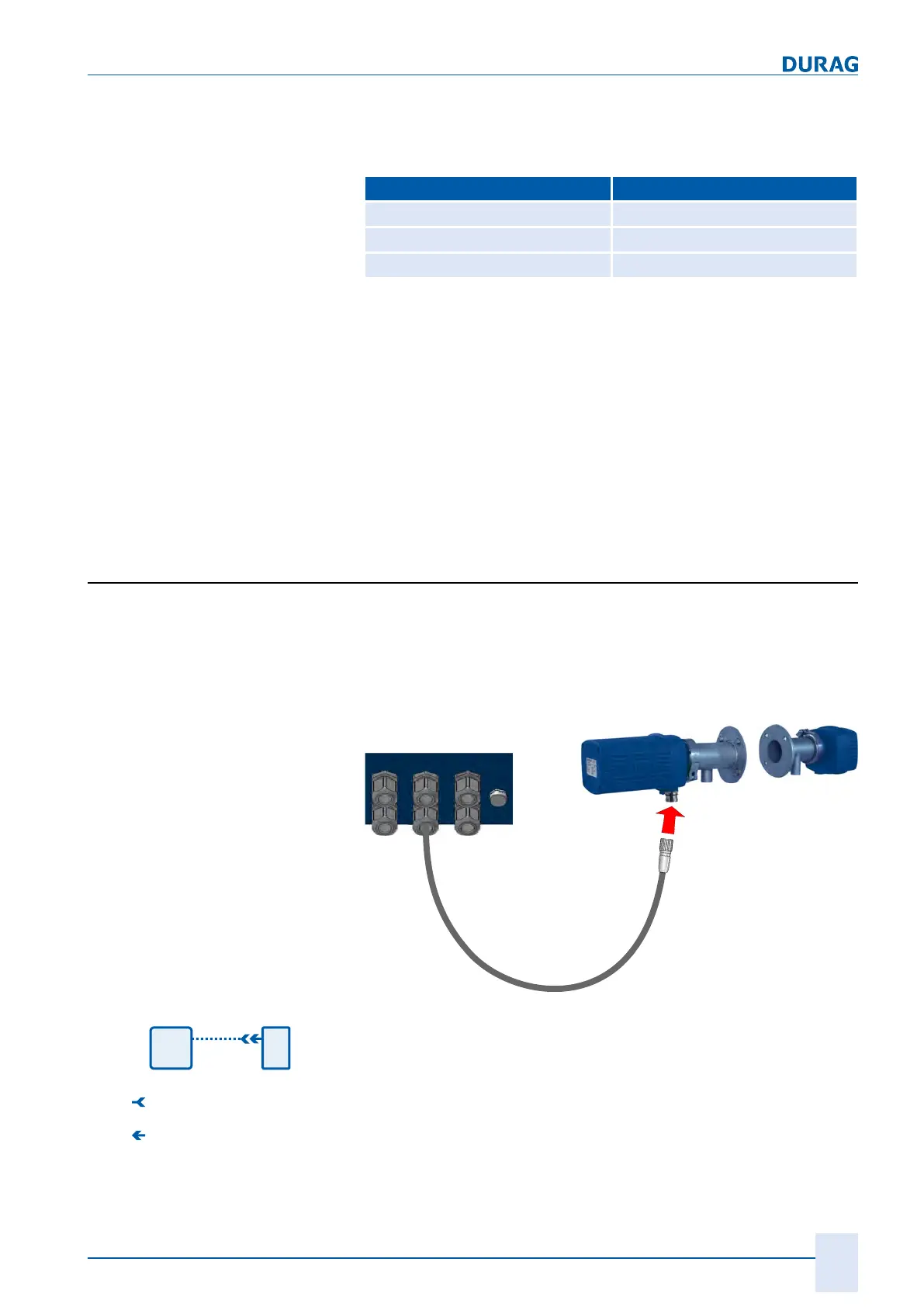
4.2.7 Individual sensor connection
For the connection of an (individual) sensor, ordered connecting
cable is connected to the Universal control unit at the factory. It
just needs to be inserted into the respective socket on the sensor
via the connector.
D-ISC 100 ...
D-R 220 M
D-ISC 100 CBL
Cable
Fig.4.8: Using the D-ISC 100 with the D-R 220
Plug connector (f)
Plug connector (m)
Fig.4.9: Individual sensor connector
1.
Insert the cable with M23 connector that has already been
connected to the D‑ISC100 at the factory into the panel jack
on the sensor (e. g. D-R 220, see figure above).
2.
Secure the connection using the connecting nut on the con-
nector.
 Loading...