10 | Channel setup menu 4
D-ISC 100 x xx2
127
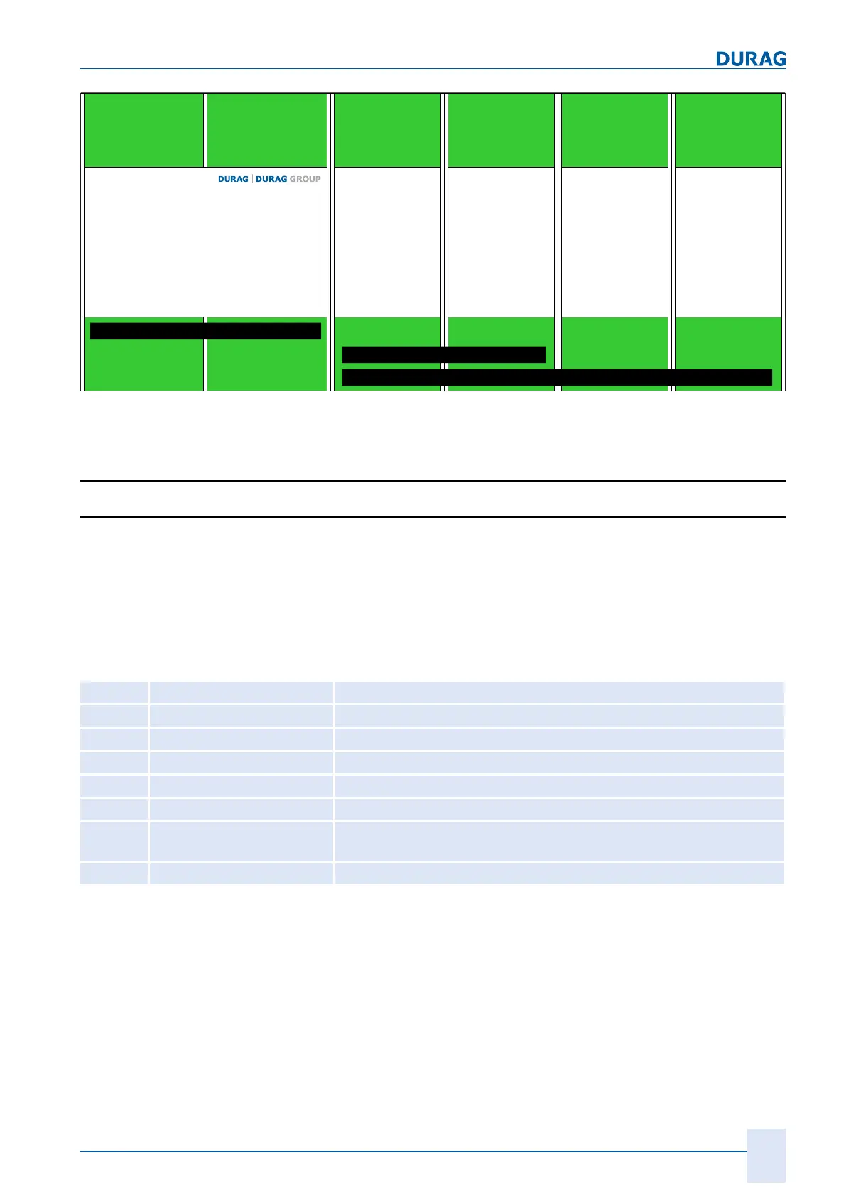
D-ISC 100 Modul
Modul 1 Modul 2 Modul 3 Modul 4
D-ISC 100 C = 0 Module
D-ISC 100 P = 2 Module
D-ISC 100 M, R = 4 Module
Fig.10.30: Module assignment; possible names and numbers of module slots for the dif-
ferent device versions
10.4.3.1 Module settings
10.4.3.1.1 Module name (e.g. AOx, MCx …)*
This description is provided by way of example. Its principle ap-
plies to all modules.
The menu items may differ depending on the module, i.e. menus
may be completely removed, submenus may be added or re-
moved.
The following abbreviations are used to designate the expansion/
software modules:
AO Analogue out Analogue output
AI Analogue in Analogue input
DO Digital out Digital output
TU Digital in Digital input
MX Mixed channel
(for measured value output
)
SX External sensors (
not DURAG sensors
)
MC Media conditions Specification of the flue gas conditions to standardise the measured
values
N Optional software modules (e.g. Modbus TCP)
Table10.2: Abbreviations of the module names
The module number and module name in the respective figures
are examples and depend on the actual configuration and selec-
tion. A possible menu number would be, e.g. 4.3.AO1…;
Selecting this menu item takes you to the channel menu for the
selected module (see also 10 Channel setup menu 4 [}96] quick
access).

 Loading...