4 | Installation and commissioning
46
D-ISC 100 x xx2
3.
If the sensor has not yet been operated with the D‑ISC100, it
will firstly need to be assigned.
✔ Following successful assignment, the new sensor can be op-
erated using the D‑ISC100.
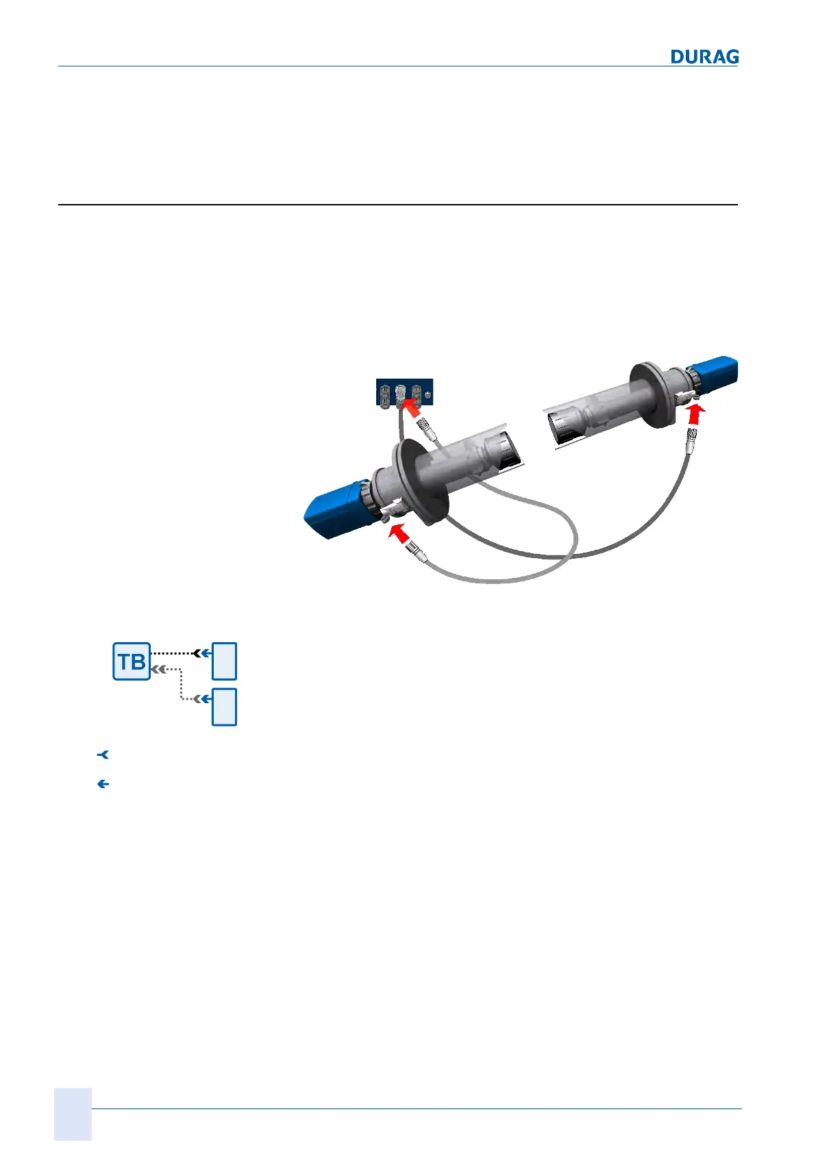
4.2.8 Dual sensor connection
With dual sensors (e.g. D-FL 220), the connection to both
sensors and both sides of the D‑ISC100 is established via plug
connector. The second sensor is connected via a separate cable
with connectors on both sides. There is also the option of con-
nection to a terminal box (D‑TBx00).
D-ISC 100 ...
D-FL 220 M
Sensor A
D-ISC 100 CBL
Cable
D-FL 220 M
Sensor B
D-TB 101 C2
Cable
Fig.4.10: Using the D-ISC 100 with the D-FL 220
Plug connector (f)
Plug connector (m)
Fig.4.11: Dual sensor plug connection
1.
Insert the connecting cable with M23 connector that has
already been connected to the D‑ISC100 at the factory into
the panel jack on the sensorA (e. g. D-FL 220, see figure
above).
2.
Secure the connection using the connecting nut on the con-
nector.
✓ The D‑ISC100 version for use with the dual sensor has an
additional M23 panel jack.
3.
Insert the cable for the D-FL 220 D‑ISC100 CBL into this
panel jack on one side.
4.
The other end of the cable is connected to the M23 panel jack
on the sensor.
5.
Secure both plug connections with the respective union nuts.
6.
If the sensor has not yet been operated with the D‑ISC100, it
will firstly need to be assigned.
✔ Following successful assignment, the new dual sensor can be
operated using the D‑ISC100.

 Loading...