4 | Installation and commissioning
D-ISC 100 x xx2
61
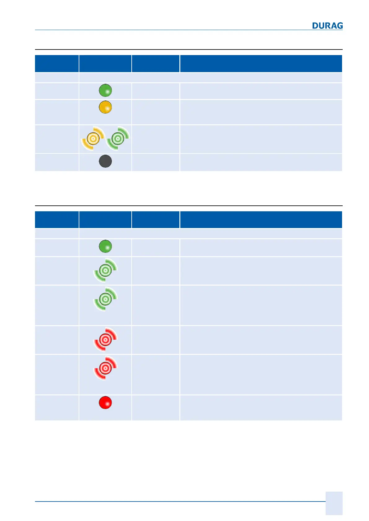
4.3.7.3.1 Meaning of system LED 1
No./
colour(s)
LED Status Meaning
1
Duo LED yellow/greenSystem LED (SYS)
green On firmware started
yellow On Status must only arise briefly
If the LED is permanently yellow, this may indicate a hard-
ware defect.
yellow/green Alternate
flashing
Bootloader active
Off Off ● no operating voltage or
● hardware defect is present.
Table4.19: Flash code meaning of system LED 1 (SYS)
4.3.7.3.2 Meaning of system LED 2
No./
colour(s)
LED Status Meaning
2
Duo LED red/greenSystem LED (APL)
green On Field bus and internal communication are operating in
cyclical data exchange
green Flashing
2s off,
0.5s on
Module initialised,
field bus
is not operating in cyclical data exchange
green flashes
2s off,
0.5s on
0.5s off
0.5s on
Module initialised,
internal communication
is not operating in cyclical data
exchange
red Flashing
2s off,
0.5s on
Module initialised,
the configuration for the
field bus protocol
is missing
red flashes
2s off,
0.5s on
0.5s off
0.5s on
Module initialised,
the configuration for the
internal communication protocol
is missing
red On An error occurred during initialisation:
● no / faulty configuration,
● internal fault
Table4.20: Flash code meaning of system LED 2 (APL)

 Loading...