4 | Installation and commissioning
D-ISC 100 x xx2
35
4.2.3 Electrical connection
DANGER
Danger of death due to electric current!
An immediate danger of death exists in case of contact with live
parts. Damage to the insulation or individual components can
present a danger of death.
▶ In the event of damage to the insulation, turn off the power
supply immediately and initiate repairs.
▶ Only have work on electric systems performed by specialised
electricians.
▶ Before opening the housing or removing the touch guard, dis-
connect the device, check that no voltage is present and se-
cure against reactivation.
▶ Keep moisture away from live parts. This may lead to a short-
circuit.
D‑ISC100 operating voltage
connection
Make sure that the D‑ISC100 is supplied with suitable electrical
voltage. Information on the necessary operating voltage and the
switching capacity of the switch contacts can be found in Section
13 Technical data [}146] and on the type label.
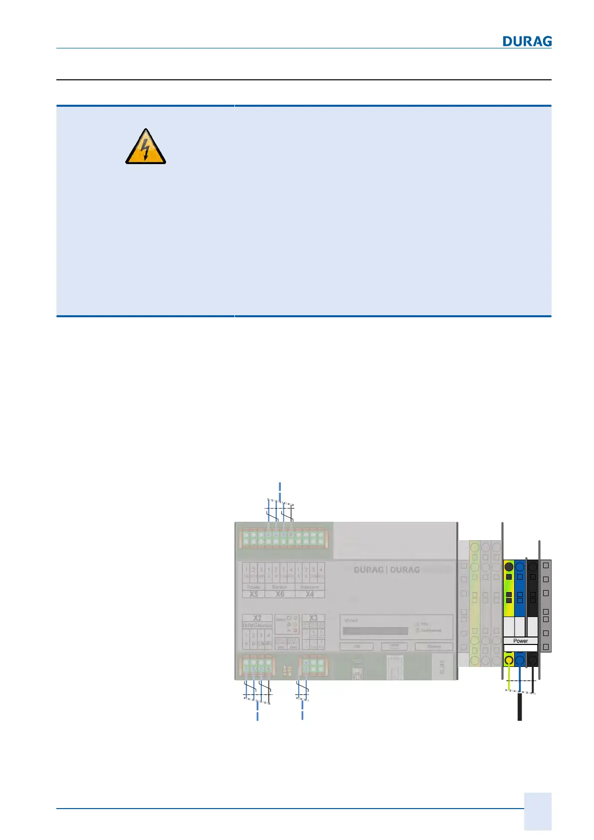
The operating voltage of the D‑ISC100 is connected to X1 via
terminal strips in the terminal compartment in accordance with
the wiring diagram.
The individual wires of the mains cable must be secured, e.g. us-
ing cable ties. When the wires are released, there must be no
contact with the adjacent terminals.
AO
0.1
DO
0.1
DO
0.2
2
-
4
CO
6
CO
1
+
3
Nx
5
Nx
1
A
2
B
3 4
1
A
2
B
3
COM
4
RFU
1
A
2
B
3
COM
4
RFU
1
PE
2
24V
3
GND
D-ISC 100 C, M, P, R
DO 0.1
NC/NO
SW1
DO 0.2
NC/NO
SW2
RJ45
Module
1
PE
2
L1
3
N
X1
Fig.4.2: Wiring diagram for the D-ISC 100 C, M, P, R operating voltage
 Loading...